Tag: Industrial Plant

  • Plant Procurement and Vendor Management: Key Practices for EPC Projects

    Plant Procurement and Vendor Management: Key Practices for EPC Projects

    Procurement is where design becomes physical. Drawings and specifications are translated into purchase orders, equipment is manufactured, and materials are delivered to site. For an EPC project, procurement is often among the largest cost elements and one of the most common sources of delay.

    Procurement and vendor management is the discipline of sourcing, purchasing, and managing the equipment, materials, and services required for a project. It includes selecting vendors, negotiating contracts, expediting deliveries, inspecting equipment, and managing vendor performance through to the end of warranty.

    For small to medium-scale industrial plants, procurement and vendor management are especially important because there is less redundancy and fewer resources to absorb the consequences of poor procurement decisions. A late delivery or defective item can delay the entire project.

    This article covers the key practices in plant procurement and vendor management, from procurement planning to vendor performance management and warranty follow-up.

    What Is Procurement and Vendor Management?

    Procurement is the process of acquiring the equipment, materials, and services needed for a project. Vendor management is the ongoing management of the suppliers who provide those goods and services.

    Together, they cover:

    • Procurement planning: Defining what to buy, when, and how.
    • Sourcing: Identifying and evaluating potential vendors.
    • Contracting: Negotiating and awarding contracts.
    • Expediting: Monitoring vendor progress and ensuring on-time delivery.
    • Inspection and surveillance: Verifying that equipment and materials meet specifications.
    • Logistics: Managing shipping, customs, and delivery to site.
    • Vendor performance management: Evaluating and managing vendor performance.
    • Warranty management: Tracking and resolving claims after delivery and installation.

    Procurement and vendor management are not just administrative functions. They directly affect project cost, schedule, quality, and risk.

    Why Procurement and Vendor Management Matter

    Factor Impact of Good Procurement Impact of Poor Procurement
    Cost Competitive pricing; no surprises Higher costs; disputes
    Schedule On-time delivery; project on track Late deliveries; project delayed
    Quality Equipment meets specifications Defective equipment; rework
    Risk Risks identified and managed Risks materialize; problems escalate
    Compliance Regulatory requirements met Non-compliance; fines
    Warranty Claims resolved quickly Warranty issues unresolved

    For small plants, where there is less margin for error, procurement and vendor management determine whether the project is delivered successfully.

    Procurement Planning

    Procurement planning defines what to buy, when, and how.

    Procurement planning activities:

    • Scope definition: What equipment, materials, and services are required?
    • Specification review: Are specifications complete and clear?
    • Make-or-buy analysis: What should be purchased vs. fabricated?
    • Packaging: How should procurement be divided into packages?
    • Scheduling: When must each item be delivered, working back from the construction schedule?
    • Budgeting: What is the budget for each item?
    • Sourcing strategy: How will vendors be identified and selected, locally or globally?
    • Contracting strategy: What contract types will be used?
    • Risk assessment: What are the procurement risks?

    Procurement planning should begin early, ideally during design, so that long-lead items are identified and ordered in time. Long-lead items (large turbines, transformers, boilers, specialty valves) often need to be ordered before detailed design is complete. Their delivery dates then drive the project schedule.

    Procurement Packages

    Procurement package types for EPC projects

    Large projects are typically divided into procurement packages.

    Package Type Description Examples
    Equipment packages Major equipment items Turbines, boilers, compressors
    Bulk materials Commodity materials Pipe, fittings, valves, cable
    Services Specialized services Inspection, NDT, machining
    Construction Construction contracts Civil, mechanical, electrical
    Systems Integrated systems Control systems, safety systems

    Packaging affects competition, coordination, and risk. Smaller packages increase competition but require more coordination. Larger packages reduce coordination but may limit competition and concentrate risk in fewer vendors.

    Procurement Documents

    Each package is defined by a set of documents sent to vendors, typically:

    • Material or purchase requisition: The technical definition of what is required.
    • Technical specifications and datasheets: Performance, design codes, materials, and testing requirements.
    • Commercial terms: Price basis, payment, delivery, warranty, and liability terms.
    • Vendor data requirements: The drawings, calculations, procedures, and manuals the vendor must submit, and when.
    • Inspection and test requirements: The quality plan or inspection and test plan (ITP) expectations.

    Incomplete or ambiguous requisitions are a leading cause of disputes and change orders, so they are worth reviewing carefully before issue.

    Vendor Identification and Prequalification

    Identifying and prequalifying vendors is critical to procurement success.

    Vendor identification sources:

    • Approved vendor lists: Vendors previously used and approved.
    • Industry directories: Trade associations, directories, and databases.
    • References: Recommendations from other plants or contractors.
    • Internet searches: Company websites and industry platforms.
    • Trade shows: Industry exhibitions and conferences.

    Vendor prequalification criteria:

    Criterion What to Assess
    Technical capability Can the vendor meet the technical requirements?
    Experience Has the vendor supplied similar equipment?
    Financial strength Is the vendor financially stable?
    Quality systems Does the vendor have a quality management system (e.g., ISO 9001)?
    Capacity Can the vendor meet the schedule given its current workload?
    References What do previous customers say?
    Compliance Does the vendor meet regulatory, safety, and ethical requirements?

    Prequalification reduces the risk of selecting an unsuitable vendor.

    Prequalification vs. Qualification

    The two terms are often used interchangeably, but they are different. Prequalification is the initial assessment of a vendor’s capability. Qualification is the ongoing process of keeping vendors on an approved list, updated as performance is evaluated and as vendors’ capabilities change. A vendor that was suitable five years ago may no longer be, so approved vendor lists should be reviewed periodically rather than treated as permanent.

    Sourcing: Global vs. Local

    Sourcing decisions involve trade-offs between global and local vendors. Global sourcing may offer lower prices and access to specialized equipment, but introduces longer lead times, customs risk, and currency exposure. Local sourcing offers shorter lead times and easier communication, but may limit competition. The right balance depends on the item and the project.

    Other factors include local content requirements, import duties and taxes, availability of local after-sales service and spare parts, and the cost of travel for inspection and expediting.

    Vendor Selection

    Vendor selection is the process of choosing the vendor for each package.

    Selection methods:

    • Competitive bidding: Multiple vendors submit proposals; the best is selected.
    • Negotiated selection: The owner negotiates with a single vendor.
    • Sole source: Only one vendor can supply the item.
    • Framework agreements: Pre-agreed terms with selected vendors.

    Evaluation criteria:

    Criterion What to Assess Indicative Weight*
    Technical compliance Does the proposal meet specifications? Pass/fail, then scored
    Price Is the price competitive, on a like-for-like basis? 30–40%
    Schedule Can the vendor meet the delivery date? 10–20%
    Experience Has the vendor done similar work? 10–15%
    Quality Does the vendor have a quality system? 10–15%
    Service Does the vendor provide support and spares? 5–10%
    Financial strength Is the vendor financially stable? 5–10%

    *Weights vary by project and package. They are shown only as an illustration.

    Evaluation is usually done in two stages. A technical evaluation checks compliance with specifications, and only technically acceptable bids go through to the commercial evaluation. This prevents a low price from outweighing a non-compliant proposal. Evaluation criteria and weights should be defined before proposals are received and applied consistently. Bid clarifications and exceptions should be documented, and prices compared on the same basis, including delivery terms, spares, and taxes.

    Contracting

    Contracting is the process of negotiating and awarding contracts.

    Contract Type Description When to Use
    Lump sum Fixed price for defined scope Well-defined scope
    Unit price Price per unit of work Quantities uncertain
    Cost plus Actual cost plus fee Scope uncertain
    Time and materials Hourly rate plus materials Small or undefined work

    Key contract terms:

    • Scope: What is included in the contract?
    • Price: How much will be paid, and when?
    • Delivery terms: Which Incoterms apply, and who bears risk and cost at each stage of transport?
    • Schedule: When must the work be completed?
    • Quality: What quality standards, inspection rights, and testing apply?
    • Warranty: What warranty is provided, for how long, and from what start date?
    • Liquidated damages: What pre-agreed compensation applies for delay or performance shortfall?
    • Performance security: Are advance payment guarantees, performance bonds, or retention required?
    • Payment terms: When and how will payment be made, and against which milestones?
    • Change management: How are changes priced and approved?
    • Termination: Under what conditions can the contract be terminated?

    Contract terms should be clear and complete to avoid disputes. Where equipment performance is guaranteed (efficiency, output, emissions), the guarantee terms and test procedures should be defined in the contract (see the article on performance guarantees in EPC contracts).

    Vendor Document Review

    After award, vendors submit drawings, calculations, and procedures for review. This step is easy to underestimate. Review turnaround times should be agreed in advance, since slow approvals delay manufacturing as surely as slow vendors do. Reviews should confirm that the design matches the specification and that interfaces (nozzle loads, foundations, electrical and instrument connections) are coordinated with the rest of the plant.

    Expediting
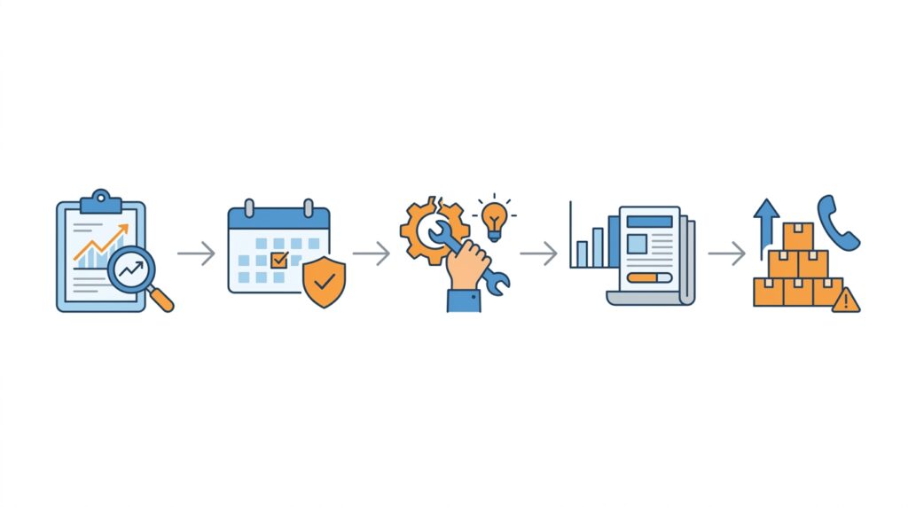
    Vendor expediting process for EPC projects

    Expediting is the process of monitoring vendor progress and ensuring on-time delivery.

    Expediting activities:

    • Progress monitoring: Tracking vendor progress against schedule.
    • Milestone verification: Confirming that milestones such as material receipt, machining, assembly, and testing are met.
    • Issue resolution: Identifying and resolving problems.
    • Reporting: Reporting progress and issues to project management.
    • Escalation: Escalating issues that cannot be resolved at the working level.

    Expediting is especially important for long-lead items, where delays have the greatest impact. A kick-off meeting with each major vendor sets expectations on schedule, reporting, and document submittals from the start. Expediters should also look at the vendor’s sub-suppliers, since delays often originate there.

    Inspection, Testing, and Surveillance

    Inspection and testing verify that equipment and materials meet specifications.

    Inspection activities:

    • Pre-inspection meeting: Reviewing inspection requirements and the ITP with the vendor.
    • In-process inspection: Inspecting during manufacturing.
    • Final inspection: Inspecting before shipment.
    • Witness testing: Witnessing tests specified in the contract, such as factory acceptance tests (FAT).
    • Documentation review: Reviewing test certificates, material certificates, and quality records.

    Inspection levels:

    Level Description
    Full inspection Every item inspected
    Sampling inspection A sample of items inspected
    Witness testing Specific tests witnessed
    Documentation review Records reviewed without physical inspection

    Inspection levels should be based on criticality and risk.

    Vendor Surveillance

    For critical equipment, vendor surveillance goes beyond inspection. It may include resident inspectors at the vendor’s facility, who monitor progress and quality throughout manufacturing. This provides earlier detection of problems than final inspection alone.

    Non-Conformance Handling

    When an inspection finds a deviation, it should be recorded in a non-conformance report. The vendor proposes a disposition (repair, rework, replace, or accept as is), and the owner or its representative approves it. Releasing equipment for shipment should depend on closing, or formally accepting, all open non-conformances.

    Logistics

    Logistics is the process of managing shipping, customs, and delivery to site.

    Logistics activities:

    • Shipping: Arranging transport from vendor to site, including special handling for oversized or heavy loads.
    • Customs: Managing import/export procedures and documentation.
    • Insurance: Insuring goods during transport.
    • Tracking: Monitoring shipment progress.
    • Receiving: Inspecting and accepting deliveries at site, and checking for shipping damage and shortages.
    • Storage and preservation: Storing materials properly and maintaining preservation measures until installation.

    Logistics is especially important for international procurement, where customs and shipping can cause significant delays. Site readiness (access roads, laydown areas, cranes, and storage) should be confirmed before deliveries arrive.

    Vendor Performance Management

    Vendor performance management is the ongoing evaluation and management of vendor performance.

    Metric What It Measures
    On-time delivery Percentage of deliveries on time
    Quality Defect rate; non-conformance rate
    Responsiveness Speed of response to issues
    Documentation Completeness and accuracy of documentation
    Warranty support Speed of warranty claims resolution
    Cost performance Adherence to contract price and control of change orders

    Performance should be reviewed regularly and used to inform future vendor selection and the qualification status of each vendor.

    Warranty Management

    Warranty management continues after equipment is delivered and installed. Warranty claims should be tracked, resolved promptly, and used to evaluate vendor performance. Warranties should be documented and their expiry dates tracked.

    Practical points include:

    • Confirm when each warranty period starts (delivery, installation, or commissioning) and when it ends.
    • Keep a register of warranties, covering equipment, vendor, terms, and expiry dates.
    • Schedule a warranty review before expiry, so latent defects are identified and claimed in time.
    • Keep operating and maintenance records, since vendors may dispute claims if equipment was operated or maintained outside their requirements.

    Managing Vendor Issues

    Vendor issues are common in procurement. Managing them effectively is critical.

    Common vendor issues:

    • Late delivery: Vendor fails to meet delivery date.
    • Quality problems: Equipment does not meet specifications.
    • Documentation gaps: Missing or incomplete documentation.
    • Communication problems: Vendor is unresponsive.
    • Financial problems: Vendor faces financial difficulty.
    • Scope disputes: Disagreement over what is included.

    Issue management approaches:

    • Early detection: Identify issues as early as possible.
    • Root cause analysis: Understand why the issue occurred.
    • Corrective action: Require the vendor to take corrective action.
    • Escalation: Escalate to higher management if needed.
    • Contract remedies: Apply contract remedies (e.g., liquidated damages).
    • Alternative sourcing: Identify alternative sources if needed.

    Issue management should be proactive, not reactive.

    Procurement and Risk Management

    Procurement is a major source of project risk.

    Risk Description Mitigation
    Late delivery Vendor fails to meet schedule Expediting; buffer; alternate vendors
    Quality problems Equipment does not meet specs Inspection; prequalification
    Cost overrun Prices increase Fixed-price contracts; contingency
    Vendor failure Vendor becomes insolvent Financial prequalification; guarantees
    Currency fluctuation Exchange rates change Hedging; currency clauses
    Logistics delays Shipping or customs delays Early ordering; tracking
    Transport damage Equipment damaged in transit or storage Insurance; packaging and handling requirements
    Force majeure Events beyond control Contract clauses; insurance

    Risk management should identify risks early and develop mitigation plans.

    Procurement Documentation

    Procurement generates significant documentation.

    Key documents:

    • Purchase orders: Formal orders for goods and services.
    • Contracts: Legal agreements with vendors.
    • Specifications and datasheets: Technical requirements.
    • Drawings: Equipment and material drawings.
    • Inspection reports: Results of inspections and tests.
    • Test certificates: Documentation of tests performed.
    • Shipping documents: Bills of lading, packing lists, certificates of origin.
    • Warranty documents: Warranty terms and conditions.
    • Vendor manuals: Operating and maintenance manuals.
    • Spare parts lists: Recommended spares for commissioning and operation.

    Documentation must be complete and accurate for handover to operations.

    Common Mistakes in Procurement and Vendor Management

    Even experienced organizations make mistakes. Common ones include:

    • Incomplete specifications: Leading to disputes and changes.
    • Inadequate prequalification: Selecting unsuitable vendors.
    • Choosing on price alone: Ignoring quality, schedule, and service.
    • Poor contract terms: Leading to disputes.
    • Slow document review: Delaying manufacturing.
    • Inadequate expediting: Discovering delays too late.
    • Skipping inspection: Accepting defective equipment.
    • Poor logistics planning: Delays in shipping or customs.
    • No performance management: Not tracking vendor performance.
    • Neglecting warranty follow-up: Letting warranty periods expire with defects unclaimed.
    • Reactive issue management: Waiting for problems to escalate.
    • Incomplete documentation: Problems during handover.

    These mistakes are costly to correct. They are much cheaper to avoid through good planning and disciplined execution.

    How Japanese EPC Firms Approach Procurement and Vendor Management

    Japanese engineering firms are known for their disciplined approach to procurement and vendor management. Common characteristics include:

    • Thorough planning: Procurement is planned carefully, with detailed specifications and schedules.
    • Careful vendor selection: Vendors are prequalified and selected based on capability, not just price.
    • Disciplined contracting: Contracts are clear and complete.
    • Active expediting: Vendor progress is monitored closely.
    • Thorough inspection: Equipment is inspected before shipment, and critical items are followed during manufacturing.
    • Detailed documentation: Records are complete and accurate.
    • Long-term relationships: Vendors are treated as partners, not just suppliers.
    • Continuous improvement: Lessons are captured and applied.

    For plant owners, this often means equipment that arrives on time, meets specifications, and performs reliably.

    How to Evaluate Procurement and Vendor Management Readiness

    When reviewing procurement and vendor management, ask:

    Question Why It Matters
    Is there a procurement plan? Provides a roadmap for procurement
    Are long-lead items identified and ordered early? Protects the project schedule
    Are specifications complete and clear? Prevents disputes and changes
    Are vendors prequalified, and is the approved list kept current? Ensures capable vendors
    Is vendor selection based on multiple criteria? Ensures the best vendor is selected
    Are contracts clear and complete? Prevents disputes
    Is expediting in place? Ensures on-time delivery
    Is inspection and surveillance planned according to criticality? Ensures equipment meets specifications
    Is logistics planned? Ensures materials arrive on time
    Is vendor performance managed? Ensures issues are addressed
    Are warranties tracked? Ensures claims are made in time
    Is documentation complete? Supports handover and operations

    A plant that addresses these questions is ready for successful procurement.

    Key Takeaways

    • Procurement and vendor management determine whether equipment arrives on time, meets specifications, and performs reliably.
    • Procurement planning should begin during design to identify long-lead items.
    • Vendor prequalification reduces the risk of selecting unsuitable vendors, and qualification keeps the approved list current.
    • Vendor selection should consider multiple criteria, not just price.
    • Clear contracts prevent disputes.
    • Expediting, inspection, and logistics ensure equipment arrives on time and in good condition. Critical equipment may justify vendor surveillance.
    • Vendor performance should be tracked and used to inform future selection.
    • Warranties should be documented, tracked, and claimed before they expire.
    • Procurement is a major source of project risk and should be managed proactively.
    • Japanese EPC firms emphasize thorough planning and long-term vendor relationships.

    Conclusion

    Procurement and vendor management are critical to EPC project success. For small to medium-scale industrial plants, they determine whether equipment and materials arrive on time, meet specifications, and perform reliably.

    By focusing on procurement planning, vendor selection, contracting, expediting, inspection, logistics, vendor performance management, and warranty follow-up, owners and project teams can ensure that procurement supports the project rather than hindering it.
  • Plant Construction Management: Key Practices for Successful Project Execution

    Plant Construction Management: Key Practices for Successful Project Execution

    Construction is where a plant moves from drawings to reality. It is the phase where steel is erected, equipment is installed, piping is connected, and systems are tested. It is also the phase where the most visible risks—safety, schedule, cost, and quality—come together.

    Construction management is the discipline of planning, coordinating, and controlling construction activities to deliver the plant safely, on schedule, within budget, and to the required quality. For small to medium-scale industrial plants, effective construction management is especially important because there is less redundancy and fewer resources to absorb the consequences of poor planning or execution.

    This article covers the key practices in plant construction management, from pre-construction planning to closeout.

    What Is Construction Management?

    Construction management is the process of managing the construction phase of a project. It includes:

    • Planning: Defining scope, schedule, budget, and resources.
    • Coordination: Managing contractors, vendors, and interfaces.
    • Control: Monitoring progress, cost, quality, and safety.
    • Communication: Keeping all parties informed.
    • Closeout: Completing punch lists and handing over to commissioning.

    Construction management is distinct from design and commissioning. It focuses on the physical execution of the work, although it must work closely with both: design provides the information to build from, and commissioning receives the finished plant.

    Why Construction Management Matters

    Construction is where projects succeed or fail.

    Factor Impact of Good Construction Management Impact of Poor Construction Management
    Safety Incidents prevented; workers protected Incidents, injuries, and regulatory action
    Schedule Milestones met; startup on time Delays cascade; startup postponed
    Cost Budget controlled; no surprises Cost overruns; disputes
    Quality Work meets specifications Rework; premature failures
    Coordination Contractors work together Conflicts; interface problems
    Documentation Records complete for handover Incomplete records; operational problems

    For small plants, where there is less margin for error, construction management determines whether the project is delivered successfully.

    The Role of the Construction Manager

    The construction manager is responsible for the construction phase of the project.

    Key responsibilities:

    • Planning and scheduling construction activities.
    • Coordinating contractors, vendors, and suppliers.
    • Monitoring progress, cost, quality, and safety.
    • Managing changes and resolving issues.
    • Reporting to the project manager and owner.
    • Ensuring documentation is complete.

    The construction manager must have both technical knowledge and management skills.

    Pre-Construction Planning

    Pre-construction planning sets the foundation for successful construction.

    Pre-construction activities:

    • Scope definition: What work is included in the construction contract?
    • Constructability review: Is the design buildable? Are there conflicts or issues?
    • Schedule development: What is the construction sequence and timeline?
    • Budget development: What is the cost of construction?
    • Contractor selection: Who will perform the work?
    • Regulatory approvals: Have building permits, environmental approvals, and other statutory requirements been obtained?
    • Site preparation: Is the site ready for construction?
    • Logistics planning: How will materials and equipment be delivered?
    • Safety planning: What are the construction hazards, and how will they be controlled?
    • Risk assessment: What could go wrong (weather, ground conditions, late deliveries, labor availability), and what is the response?

    Pre-construction planning should begin early—ideally during design—to identify and resolve issues before construction starts.

    Constructability Review

    A constructability review examines the design to identify construction issues before they become problems.

    Constructability review questions:

    • Can the design be built safely and efficiently?
    • Are there conflicts between disciplines (e.g., piping and structural)?
    • Is there adequate access for construction equipment, including cranes?
    • Are there adequate laydown areas?
    • Are materials and equipment available within the required lead times?
    • Are there sequencing issues?
    • Is there space and access to maintain the equipment once installed?
    • Are there constructability issues that will increase cost or schedule?

    Constructability reviews are most valuable when conducted during design, when changes are still inexpensive.

    Construction Sequencing

    Construction sequencing determines the order in which work is performed. Good sequencing minimizes rework, avoids blocking access, and allows work to proceed in parallel where possible. Sequencing should be planned during pre-construction and adjusted as work progresses.

    Typical sequencing considerations for an industrial plant include:

    • Installing underground utilities and foundations before structures and equipment are placed above them.
    • Setting heavy equipment (turbines, boilers, large vessels) before surrounding structures and piping close off crane access.
    • Completing large-bore piping and structural steel before small-bore piping, cable trays, and instrumentation.
    • Prioritizing work by system, so that areas and systems can be completed and turned over to commissioning in the order commissioning needs them.

    Sequencing should be aligned with equipment delivery dates, so that work is not delayed waiting for materials and equipment is not stored longer than necessary.

    Construction Organization

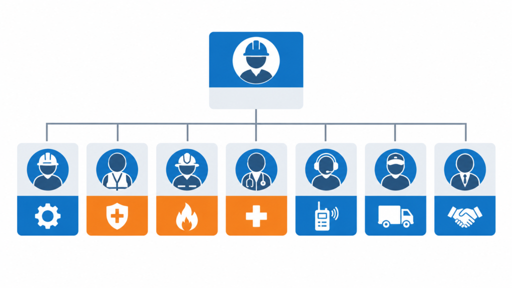
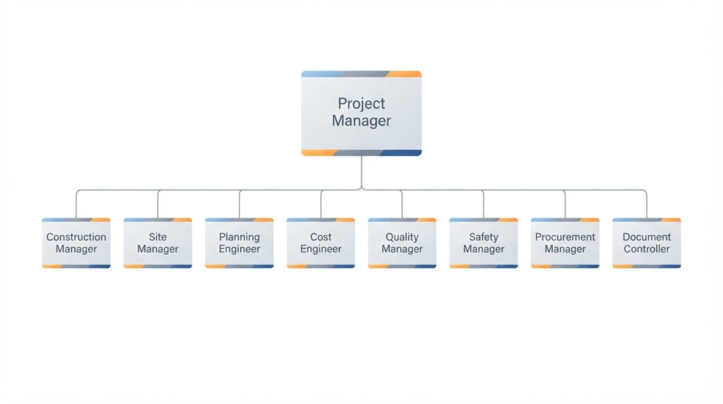
    Construction management organization structure for industrial plants

    A clear organization is essential for construction management.

    Key roles:

    Role Responsibility
    Project Manager Overall responsibility for the project
    Construction Manager Construction planning, coordination, and control
    Site Manager Day-to-day management of the site
    Planning Engineer Schedule development and progress tracking
    Cost Engineer Budget tracking and cost control
    Quality Manager Quality control and inspection
    Safety Manager Safety oversight and compliance
    Procurement Manager Materials and equipment
    Document Controller Document management

    For small plants, roles may be combined, but the functions must be covered. Clear lines of authority and reporting should be established before mobilization, so that everyone on site knows who makes decisions.

    Temporary Facilities

    Construction sites require temporary facilities. Temporary facilities—site offices, warehouses, rest areas, first aid stations, and utilities—must be planned and provided. These facilities support the construction workforce and are demobilized during closeout.

    Other temporary facilities to plan for include:

    • Laydown and fabrication yards.
    • Temporary power, water, and sanitation.
    • Site access roads, gates, and security.
    • Waste collection and storage.
    • Parking, worker transport, and, for remote sites, accommodation.

    These facilities should be located so that they do not interfere with permanent works, and their cost and schedule impact should be included in the construction plan.

    Contractor Management

    Construction is typically performed by contractors. Managing them effectively is critical.

    Contractor management activities:

    • Pre-qualification: Assessing contractor capability, safety record, and financial strength.
    • Contracting: Defining scope, schedule, quality, and safety requirements.
    • Mobilization: Ensuring contractors are ready to start work, with qualified personnel, equipment, and approved procedures.
    • Supervision: Monitoring contractor performance.
    • Coordination: Managing interfaces between contractors.
    • Performance evaluation: Assessing contractor performance against requirements.

    Good contractor management requires clear expectations, consistent enforcement, and open communication. Contractors should also be required to submit method statements for critical or high-risk activities, such as heavy lifts, so that the approach is reviewed before work begins.

    Interface Management

    Construction interface management between disciplines

    Construction involves many interfaces—between disciplines, contractors, and systems.

    Common interfaces:

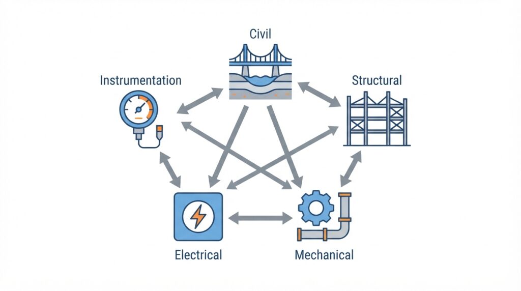
    • Between civil and structural works.
    • Between structural and mechanical works.
    • Between mechanical and electrical works.
    • Between electrical and instrumentation works.
    • Between contractors working in the same area.
    • Between construction and commissioning.
    • Between new construction and existing operating facilities, where applicable.

    Interface management ensures that work is coordinated and conflicts are resolved. Practical tools include an interface register, regular coordination meetings, and area-based work planning.

    Schedule Management

    Schedule management ensures that construction is completed on time.

    Schedule management activities:

    • Baseline schedule: The approved schedule for the project.
    • Progress tracking: Measuring actual progress against the baseline, using agreed progress measurement rules (for example, weighted quantities installed rather than subjective estimates).
    • Critical path analysis: Identifying activities that determine the project duration.
    • Schedule updates: Updating the schedule as work progresses.
    • Look-ahead planning: Short-term (for example, three-week) schedules that translate the baseline into detailed work plans.
    • Delay analysis: Identifying causes of delay and corrective actions.
    • Recovery planning: Developing plans to recover schedule slippage.

    Schedule management requires accurate progress data and timely decision-making.

    Cost Management

    Cost management ensures that construction is completed within budget.

    Cost management activities:

    • Budget development: The approved budget for construction.
    • Commitment tracking: Tracking contracts and purchase orders.
    • Cost tracking: Tracking actual costs against budget.
    • Forecasting: Predicting final costs based on current trends.
    • Change management: Managing scope changes and their cost impact.
    • Contingency management: Managing contingency for unknowns.

    Cost management requires accurate cost data and disciplined change control. Cost and schedule performance are best evaluated together—for example, by comparing the value of work completed with both planned progress and actual spending—so that problems are visible early.

    Quality Management

    Quality management ensures that construction meets specifications.

    Quality management activities:

    • Quality plan: Defining quality requirements and responsibilities.
    • Inspection and test plans: Defining which activities are inspected, by whom, and at which hold or witness points.
    • Inspection and testing: Verifying that work meets specifications.
    • Documentation: Recording inspections and test results.
    • Non-conformance management: Identifying and resolving quality issues.
    • Final acceptance: Confirming that work meets requirements.

    Quality issues discovered during construction are cheaper to fix than those discovered during commissioning or operation. Inspecting work as it is completed, rather than at the end, prevents defects from being buried by later work.

    Safety Management

    Safety is the highest priority in construction.

    Safety management activities:

    • Hazard identification: Identifying construction hazards.
    • Risk assessment: Assessing and prioritizing risks.
    • Safety procedures: Permit-to-work, lockout/tagout, confined space, hot work, work at height, excavation, and lifting operations.
    • Training: Ensuring workers are trained for their tasks and receive a site induction.
    • PPE: Providing and enforcing use of protective equipment.
    • Inspections: Regular site inspections to identify hazards.
    • Incident reporting: Reporting and investigating incidents and near-misses.
    • Emergency response: Planning for emergencies.

    Safety must be integrated into every construction activity, not added as an afterthought.

    Permit-to-Work Systems

    Permit-to-work is a key safety control during construction. A permit-to-work system controls high-risk activities such as hot work, confined space entry, and work at height. Permits define the precautions required and must be issued by authorized personnel before work begins.

    An effective permit-to-work system also:

    • Specifies the location, scope, duration, and the people covered by each permit.
    • Requires the area to be checked and isolated as needed before work starts.
    • Coordinates simultaneous operations, so that one activity does not endanger another.
    • Requires permits to be closed out when work is complete or suspended.

    Environmental Management

    Construction can affect the environment through dust, noise, spills, waste, and runoff. An environmental plan should address permit conditions, waste management, spill prevention, and erosion and sediment control. Environmental requirements should be communicated to contractors and monitored like any other contract requirement.

    Materials and Equipment Management

    Construction requires timely delivery of materials and equipment.

    Materials management activities:

    • Procurement: Ordering materials and equipment.
    • Expediting: Monitoring supplier progress.
    • Inspection: Verifying materials meet specifications.
    • Logistics: Managing shipping, customs, and delivery.
    • Receiving: Inspecting and accepting deliveries.
    • Storage: Storing and preserving materials.
    • Issue: Delivering materials to the work site.

    Materials management ensures that materials are available when needed and in good condition. Rotating equipment, electrical gear, and instruments often require special preservation (for example, climate-controlled storage or periodic rotation), and failing to maintain it can invalidate warranties.

    Construction Documentation

    Construction generates vast amounts of documentation.

    Key documents:

    • Drawings: As-built drawings reflecting actual construction.
    • Specifications: Technical requirements.
    • Inspection records: Results of inspections and tests.
    • Test records: Results of system tests.
    • Non-conformance reports: Records of quality issues.
    • Change orders: Documentation of scope changes.
    • Progress reports: Records of progress and issues.
    • Safety records: Incident reports and safety inspections.
    • Vendor documents: Manuals, certificates, and warranty information.

    Documentation must be complete and accurate for handover to commissioning and operations. It is far easier to collect records as the work is completed than to reconstruct them afterward.

    Communication and Reporting

    Regular communication keeps everyone aligned. Typical practices include daily toolbox or coordination meetings, weekly progress meetings with contractors, and monthly reports to the owner covering progress, cost, quality, safety statistics, risks, and upcoming milestones. Decisions and actions should be recorded and followed up.

    Managing Changes During Construction

    Changes during construction are common. Managing them is critical.

    Change management activities:

    • Change identification: Recognizing when a change is required.
    • Change assessment: Evaluating the impact on scope, schedule, cost, quality, and safety.
    • Change approval: Approving or rejecting the change.
    • Change implementation: Implementing the change.
    • Documentation: Recording the change and its impact, including updates to drawings.

    Uncontrolled changes lead to scope creep, schedule delays, and cost overruns.

    Construction Closeout

    Closeout is the phase where construction is completed and handed over to commissioning.

    Closeout activities:

    • Punch list: Outstanding items to be completed, typically categorized by whether they must be finished before commissioning or can be completed afterward.
    • Inspection: Verification that work meets requirements.
    • Mechanical completion: Confirmation that systems are built, inspected, and ready for pre-commissioning and commissioning.
    • Documentation: Completion of as-built drawings and records.
    • Handover: Formal transfer to commissioning, typically system by system.
    • Demobilization: Removal of contractors, equipment, and temporary facilities.
    • Housekeeping: Cleaning the site.

    Closeout should be planned as part of construction, not left to the end. Handing over completed systems progressively allows commissioning to start earlier and reduces the end-of-project crunch.

    Lessons Learned

    Lessons learned during construction should be captured and applied. Regular reviews and a lessons-learned database help ensure that problems are not repeated on future projects.

    Lessons should be captured throughout the project, not only at the end—for example, at milestone reviews and after significant incidents or non-conformances—and shared with the people who will plan the next project.

    Common Mistakes in Construction Management

    Even experienced organizations make mistakes. Common ones include:

    • Inadequate pre-construction planning: Starting construction before planning is complete.
    • Poor constructability review: Missing design issues that cause problems during construction.
    • Unclear scope: Leading to disputes and changes.
    • Poor contractor selection: Choosing on price alone.
    • Inadequate interface management: Conflicts between disciplines and contractors.
    • Poor sequencing: Work performed in an order that causes rework or blocks access.
    • Poor schedule management: Delays not identified or addressed.
    • Weak cost control: Cost overruns not detected until too late.
    • Quality issues: Rework and premature failures.
    • Safety shortcuts: Leading to incidents.
    • Incomplete documentation: Problems during handover.
    • Failing to capture lessons: Repeating the same mistakes on later projects.

    These mistakes are costly to correct. They are much cheaper to avoid through good planning and disciplined execution.

    How Japanese EPC Firms Approach Construction Management

    Japanese engineering firms are known for their disciplined approach to construction management. Common characteristics include:

    • Thorough planning: Construction is planned carefully, with detailed schedules and work packages.
    • Disciplined execution: Work is performed as planned, with tight control.
    • Safety focus: Safety is prioritized throughout, with daily toolbox meetings and hazard prediction activities.
    • Quality control: Work is inspected as it is completed.
    • Detailed documentation: Records are complete and accurate.
    • Interface management: Interfaces between disciplines and contractors are carefully managed.
    • Continuous improvement: Lessons are captured and applied.
    • Long-term focus: Construction is treated as the foundation for reliable operation.

    For plant owners, this often means construction that is completed safely, on schedule, within budget, and to the required quality.

    How to Evaluate Construction Management Readiness

    When reviewing construction management, ask:

    Question Why It Matters
    Is pre-construction planning complete? Sets the foundation for success
    Has a constructability review been performed? Identifies issues before construction
    Is the scope clearly defined? Prevents disputes and changes
    Are contractors pre-qualified? Ensures capable contractors
    Is the construction sequence defined? Minimizes rework and access conflicts
    Is the schedule realistic? Ensures work can be completed
    Is the budget adequate? Ensures funding is available
    Are temporary facilities planned? Supports the workforce and logistics
    Is there a quality plan? Ensures work meets specifications
    Is there a safety plan and permit-to-work system? Protects workers
    Are interfaces managed? Prevents conflicts
    Is documentation complete? Supports handover and operations
    Is there a process for capturing lessons learned? Improves future projects

    A plant that addresses these questions is ready for successful construction.

    Conclusion

    Construction management is the discipline of delivering the plant safely, on schedule, within budget, and to the required quality. For small to medium-scale industrial plants, it is especially important because there is less margin for error.

    By focusing on pre-construction planning, constructability review, sequencing, contractor management, interface management, schedule, cost, quality, and safety, owners and construction managers can ensure that construction is completed successfully and the plant is ready for commissioning and operation.

    Key Takeaways

    • Construction management delivers the plant safely, on schedule, within budget, and to quality.
    • Pre-construction planning sets the foundation for success.
    • Constructability reviews identify issues before construction begins.
    • Good sequencing minimizes rework and avoids blocking access.
    • Contractor, interface, schedule, cost, quality, and safety management are all essential.
    • Permit-to-work systems control high-risk activities.
    • Materials management ensures materials are available when needed.
    • Documentation must be complete and accurate for handover.
    • Change management prevents scope creep and cost overruns.
    • Closeout should be planned as part of construction.
    • Lessons learned should be captured and applied to future projects.
    • Japanese EPC firms emphasize thorough planning and disciplined execution.
  • Plant Life Extension: Strategies for Extending the Life of Aging Industrial Plants

    Plant Life Extension: Strategies for Extending the Life of Aging Industrial Plants

    Most industrial plants are designed for a finite life, typically 20 to 40 years depending on the industry, the equipment and the design basis. Many plants operate well beyond that. Equipment is replaced, systems are upgraded, and the plant continues to produce. Others reach a point where life extension is no longer economic, and replacement becomes the better option.

    Plant life extension (PLEX) is the process of assessing, planning, and executing the work needed to keep an aging plant operating safely, reliably, and economically beyond its original design life. It is a strategic decision that affects capital investment, operating cost, safety, and regulatory compliance.

    For small to medium-scale industrial plants, life extension decisions are especially important because there is less redundancy and fewer resources to absorb the consequences of a wrong decision. Extending the life of a plant that should be replaced wastes money. Replacing a plant that could be extended safely wastes capital.

    This article covers the key considerations in plant life extension, from assessment to execution.

    What Is Plant Life Extension?

    Plant life extension is the set of activities required to continue operating a plant beyond its original design life while maintaining safety, reliability, and compliance.

    It is worth separating two terms. Design life is the period the plant was originally designed and analyzed for. Useful life is how long the plant can actually operate safely and economically. Design life is a starting assumption, not a hard limit. Some equipment fails earlier because of poor operation or maintenance, and well-maintained equipment often lasts much longer.

    Life extension is not simply “keeping the plant running.” It involves:

    • Assessment: Evaluating the condition and remaining life of equipment and systems.
    • Planning: Identifying what work is needed and when.
    • Investment: Funding the required repairs, replacements, and upgrades.
    • Execution: Performing the work, often during turnarounds.
    • Monitoring: Tracking performance and condition over time.

    Life extension can range from a few years of incremental work to a major program of replacement and upgrade.

    Why Life Extension Matters

    Life extension decisions have significant consequences.

    Factor Impact of Good Life Extension Impact of Poor Life Extension
    Safety Equipment maintained within safe limits Aging equipment creates safety risks
    Reliability Failures managed before they occur Increasing failures and unplanned outages
    Cost Capital deployed where it adds most value Money wasted on the wrong equipment
    Compliance Regulatory requirements met Non-compliance, fines, or forced shutdown
    Production Output maintained or improved Declining performance and output
    Business case Investment justified and returns achieved Poor returns; capital stranded
    Insurance and financing Insurers and lenders confident in the plant’s condition Higher premiums, restricted cover, or difficulty financing

    For small plants, life extension is often the main alternative to building a new plant, which may be prohibitively expensive.

    The Case for Life Extension

    Life extension is often justified when:

    • The plant is in good condition: Equipment has been well maintained.
    • The remaining life is sufficient: The plant can operate for years with targeted investment.
    • Replacement is expensive: Building a new plant is not economically viable.
    • Demand exists: The plant’s output is still needed.
    • Regulatory compliance is achievable: The plant can meet current and foreseeable requirements.
    • Upgrades add value: Efficiency, capacity, or flexibility improvements justify investment.

    Life extension is not always the right choice. Sometimes replacement is better, especially if the plant is in poor condition, compliance is not achievable, or demand is declining.

    The Case Against Life Extension

    Life extension may not be justified when:

    • The plant is in poor condition: Equipment is degraded beyond economic repair.
    • Compliance is not achievable: The plant cannot meet current or foreseeable regulations.
    • Replacement is cheaper: The cost of life extension, including the risk of future outages, exceeds the cost of a new plant.
    • Demand is declining: The plant’s output is no longer needed.
    • Technology is obsolete: Spare parts, expertise, and support are unavailable.
    • Safety risks are unacceptable: The plant cannot be operated safely.

    The decision requires an honest assessment of both the plant and the business case.

    Key Drivers of Plant Aging

    Key drivers of plant aging in industrial plants

    Plants age for several reasons.

    Driver Description Examples
    Physical degradation Wear, corrosion, fatigue, erosion, and other damage mechanisms Pipe wall thinning, bearing wear, refractory degradation, creep in high-temperature piping, thermal fatigue, embrittlement, hydrogen damage
    Obsolescence Technology no longer supported Control systems, instrumentation, spare parts
    Regulatory changes New or stricter requirements Emissions limits, safety standards
    Economic changes Market, fuel, or cost changes Fuel price increases, competition
    Technology changes New technology makes old obsolete More efficient equipment, digital controls
    Organizational changes Loss of expertise, changing priorities Retirement of experienced staff

    Understanding which drivers apply to your plant helps focus life extension efforts. Physical degradation is the one most people think of first, but obsolescence and organizational change can cause problems sooner than expected.

    Assessing Remaining Life

    The first step in life extension is assessing the condition and remaining life of equipment and systems.

    Method Description Application
    Condition assessment Physical inspection and testing Piping, vessels, structures
    Remaining life analysis Engineering calculations based on condition Pressure vessels, piping, turbines
    Failure history review Analysis of past failures and repairs All equipment
    Performance testing Measuring current performance Turbines, compressors, heat exchangers
    Obsolescence review Identifying equipment at risk of obsolescence Control systems, instrumentation
    Compliance review Identifying regulatory gaps All systems

    Assessment should cover all major equipment and systems, not just the most visible ones. It also depends on good records. Original design data, as-built drawings, operating history, inspection reports, and repair records are the baseline against which condition is judged. If they are missing or unreliable, rebuilding them is the first job of the assessment.

    Design Basis and Code Gap Review

    A plant built 30 years ago was designed to the codes, standards, and practices of that time. Before committing to life extension, compare the original design basis with current requirements. Common gaps include pressure equipment codes, fire protection and electrical standards, safety instrumented system requirements, structural and seismic criteria, and environmental limits.

    Not every gap must be closed. Legal requirements for older plants vary by jurisdiction and by whether the work is a modification or a continuation of existing operation. A documented gap review helps the owner and the regulator agree on what must be upgraded, what can be justified by other measures, and what is acceptable as is. Skipping this review is a common way for hidden compliance costs to surface mid-program.

    Fitness-for-Service Assessment

    Fitness-for-service (FFS) assessment evaluates whether equipment with known defects or degradation can continue to operate safely. Standards such as API 579-1/ASME FFS-1 provide methodologies for assessing remaining strength and life. FFS is especially useful for pressure equipment with corrosion, cracking, or wall loss. It can show that equipment is acceptable as is, acceptable with a reduced operating envelope or a shorter inspection interval, or in need of repair or replacement. That often avoids unnecessary replacement and supports a defensible decision.

    Risk-Based Inspection

    Risk-based inspection (RBI) prioritizes inspection based on the likelihood and consequence of failure. It helps direct limited inspection resources to the equipment that matters most. Recognized practices such as API 580 and API 581 provide the framework. For small plants with limited inspection budgets, RBI helps ensure the highest-risk equipment gets the most attention while low-risk items are inspected less often.

    Using Remaining Life in Maintenance Planning

    Remaining life assessment should feed directly into maintenance planning and drive decisions: equipment approaching the end of its remaining life should be scheduled for replacement or refurbishment, not just monitored. Remaining life estimates are not fixed. They should be updated as new inspection data, operating history, and changes in operating conditions become available.

    Inspection, Testing, and Monitoring Techniques

    Remaining life estimates are only as good as the data behind them. Common techniques include:

    Technique Typical Use
    Visual and remote inspection (borescope, drones, crawlers) Vessels, tanks, stacks, boilers, hard-to-reach areas
    Ultrasonic thickness and flaw detection Wall loss, cracking, weld quality
    Radiography and magnetic particle / dye penetrant testing Welds, surface cracks
    Metallurgical methods (hardness, replication, sampling) Creep damage, embrittlement, material degradation in high-temperature service
    Vibration, thermography, oil analysis Rotating equipment, electrical connections, lubrication condition
    Electrical testing (insulation resistance, partial discharge, transformer oil analysis) Transformers, motors, cables, switchgear
    Structural surveys and concrete/steel testing Foundations, pipe racks, buildings, stacks
    Online and continuous monitoring Tracking trends between inspections

    Where data is limited, inspect more or use more conservative assumptions. For equipment with significant temperature or pressure cycling, track accumulated damage (starts, stops, and load changes), because operating history consumes life as well as calendar age.

    Critical Equipment and Systems

    Some equipment and systems are more critical to life extension than others. Common critical items include:

    • Pressure vessels and piping: Subject to corrosion, fatigue, creep, and regulatory inspection.
    • Rotating equipment: Turbines, compressors, pumps, and motors.
    • Boilers and heat exchangers: Subject to fouling, corrosion, and thermal fatigue.
    • Electrical systems: Transformers, switchgear, motors, and cables, including insulation aging.
    • Control systems: Often the first to become obsolete.
    • Structures and foundations: Subject to corrosion and structural degradation.
    • Safety systems: Must be maintained and updated to current standards.
    • Long-lead and non-redundant items: Equipment that is hard to replace quickly or whose failure stops the whole plant.

    Critical items should be assessed first and in more detail. A useful way to rank them is by combining the consequence of failure (safety, environment, production, cost) with the likelihood of failure based on condition.

    Equipment-Specific Life Considerations

    Equipment Typical Life-Limiting Mechanisms Typical Life Extension Actions
    Boilers and heat recovery equipment Tube wall loss, creep, thermal fatigue, fireside and waterside corrosion Tube replacement, header and weld inspection, water chemistry improvement
    Steam and gas turbines Creep, low-cycle fatigue, erosion, blade damage Major overhauls, component replacement, rotor life assessment
    Pressure vessels and piping Corrosion, cracking, creep (high temperature), fatigue FFS assessment, repair, re-rating, replacement of sections
    Pumps, compressors, motors Wear, vibration, bearing and seal failure, insulation aging Refurbishment, rewinding, re-rating or replacement
    Transformers and switchgear Insulation degradation, contact wear, moisture Testing, oil treatment, refurbishment, replacement
    Control and instrumentation Obsolescence, component failure Phased or full migration to modern systems
    Structures and foundations Corrosion, concrete deterioration, settlement Surveys, repair, strengthening, protective coatings

    This table is a starting point. The right actions depend on the equipment’s condition and duty.

    Life Extension Strategies

    Life extension strategies for aging industrial plants

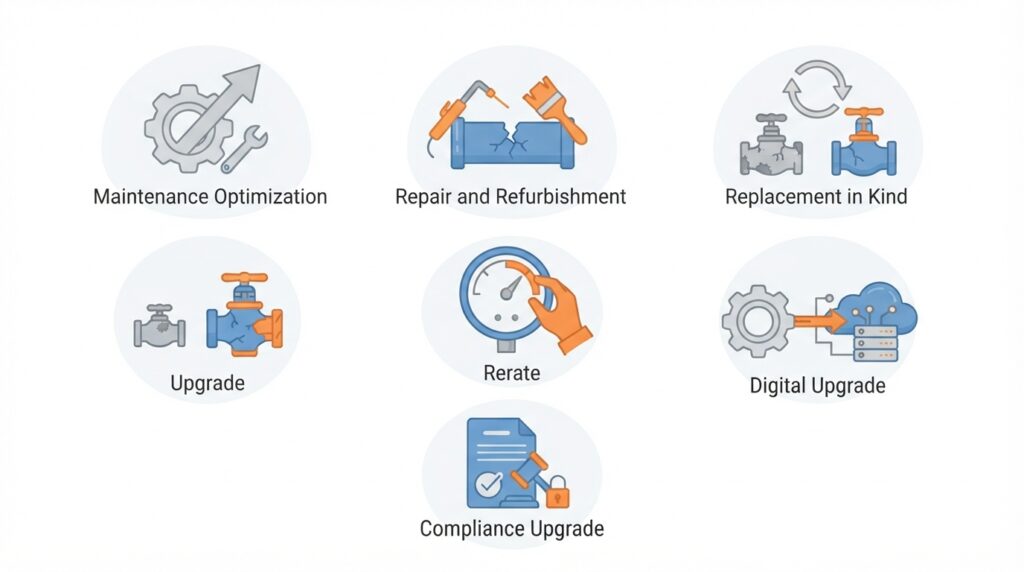
    Several strategies can be used to extend plant life.

    Strategy Description When to Use
    Maintenance optimization Improve maintenance to extend equipment life When equipment is in reasonable condition
    Repair and refurbishment Repair or refurbish degraded equipment When repair is cheaper than replacement
    Replacement in kind Replace with identical or equivalent equipment When the original design is still suitable
    Upgrade Replace with improved equipment When improvements justify investment
    Rerate Increase capacity or efficiency When demand or economics justify
    Digital upgrade Modernize controls and monitoring When obsolescence is a concern
    Compliance upgrade Meet new regulatory requirements When regulations require it

    A rerate changes the conditions the plant was designed for, so pressure relief, piping, electrical, and control systems must be rechecked against the new operating envelope.

    Strategies can be combined. A life extension program may include maintenance optimization, targeted replacement, and control system upgrades. Any change to equipment, design, or operating conditions should go through a formal management of change (MOC) process. Major work should be followed by a pre-startup safety review (PSSR) before the plant returns to service.

    Planning Life Extension

    Life extension should be planned as a program, not a series of individual projects.

    Planning elements:

    • Objectives: What is the target life extension (for example, 10 years or 20 years)?
    • Scope: What work is required to achieve the objectives?
    • Schedule: When will the work be performed?
    • Budget: What is the cost, and how will it be funded?
    • Resources: Who will do the work, and what skills are needed?
    • Risk: What are the risks, and how will they be managed?
    • Approvals: Who approves the plan, and what is the process?

    Planning should begin well before the plant reaches the end of its original design life. Many owners find a staged approach practical:

    1. Screening: A high-level review of condition, compliance, obsolescence, and economics to decide whether life extension is worth pursuing.
    2. Detailed assessment: Inspection, testing, remaining life analysis, and FFS work on critical equipment.
    3. Program definition: Scope, schedule, budget, and risk plan based on the assessment.
    4. Execution: Work performed in a controlled way, usually during turnarounds.
    5. Monitoring and review: Condition and performance tracked, and the program updated as findings change.

    Staging lets the owner stop early if the screening or assessment shows that replacement is the better option, before large sums are spent.

    Spare Parts Strategy

    Life extension programs should include a spare parts strategy. Parts for aging equipment may have long lead times or may be obsolete, and should be identified and procured well before they are needed. A good strategy identifies critical spares, reviews what is in stock, checks supplier availability, and decides which parts to buy now, which to source on demand, and which to replace through upgrades. It should be built into the program budget from the start, not discovered when a failure occurs.

    Life Extension and Turnarounds

    Turnarounds are often the best opportunity to perform life extension work.

    Advantages:

    • The plant is already shut down.
    • Access to equipment is available.
    • Contractors and resources are mobilized.
    • Work can be coordinated with other maintenance.

    Considerations:

    • Turnaround scope may need to be expanded.
    • Planning must begin earlier.
    • Budget must be secured in advance.
    • Work must be sequenced with other turnaround activities.
    • Long-lead items must be ordered well before the shutdown.

    Life extension work that is not done during a turnaround may require a separate outage, which adds cost and lost production. Turnaround inspection findings should also feed back into the remaining life assessment.

    Executing Life Extension: Contracting, Contingency, and Quality

    Life extension work differs from new construction because the full scope is not known until equipment is opened up. This affects how work should be organized:

    • Scope growth is normal. Discovery work (additional repairs found during inspection) should be expected. Budgets and schedules need larger contingency than for comparable new work, and contracts should say how additional scope is priced and approved.
    • Phase the work. Early phases (inspection and assessment) can confirm scope before major purchases or contracts are committed.
    • Control quality. Materials, welding, and repair procedures should meet applicable codes, with traceability and qualified personnel. Repairs to aging equipment often involve older materials, so compatibility and welding procedures need care.
    • Plan restart carefully. After major work, a PSSR, commissioning checks, and performance testing confirm the plant is ready and that expected benefits were achieved.
    • Choose the delivery model deliberately. Depending on the owner’s own engineering capability, the work may be self-managed, split among specialist contractors, or given to an EPC contractor.

    Life Extension and Obsolescence

    Obsolescence is one of the biggest challenges in life extension.

    Common obsolescence issues:

    • Control systems: Older systems may no longer be supported.
    • Instrumentation: Older instruments may be discontinued.
    • Spare parts: Parts may no longer be available.
    • Software: Older software may not run on modern platforms.
    • Expertise: Fewer people know how to maintain older systems.

    Obsolescence strategies:

    • Identify at-risk items: Which equipment is at risk of obsolescence?
    • Last-time buy: Purchase spare parts before discontinuation.
    • Alternate sources: Identify substitute parts or suppliers.
    • Upgrade: Replace obsolete equipment with modern equivalents.
    • Reverse engineering: Manufacture equivalents when needed, with attention to material qualification, quality, and intellectual property.
    • Redesign: Modify systems to use available technology.

    Obsolescence should be addressed proactively, not reactively.

    Digital Upgrades and Cybersecurity

    Replacing obsolete control systems usually brings networked, software-based equipment into the plant. This improves monitoring and reliability, but it also brings cybersecurity risk that older standalone systems did not have. A digital upgrade should include network segmentation, access control, patch management, backup and recovery, and training for operations and maintenance staff.

    Life Extension and Regulatory Compliance

    Regulatory requirements often drive life extension decisions.

    Common regulatory issues:

    • Emissions limits: New or stricter limits may require equipment upgrades.
    • Safety standards: New standards may require safety system upgrades.
    • Inspection requirements: Older equipment may require more frequent inspection.
    • Environmental requirements: New requirements may affect water, waste, or emissions.
    • Operating permits and licenses: Some jurisdictions require formal review or renewal to operate beyond the design life.

    Compliance strategies:

    • Identify gaps: What requirements does the plant not currently meet?
    • Assess options: What are the options for achieving compliance?
    • Plan upgrades: When and how will upgrades be performed?
    • Monitor changes: Keep track of regulatory developments.

    Compliance should be addressed as part of the life extension program, not as a separate effort.

    Safety and Risk Review

    Life extension must not only keep the plant running but also keep its risk acceptable. Aging increases the likelihood of some failures, and changes made during life extension can introduce new risks.

    Good practice includes:

    • Revalidating hazard studies (such as HAZOP) for the plant as it now exists, including past modifications.
    • Reviewing safety systems. Check that relief devices, alarms, interlocks, and safety instrumented functions still meet their required performance, and re-verify them where components are replaced or conditions have changed.
    • Reviewing fire protection and emergency response against the current plant layout and inventory.
    • Controlling work hazards. Older plants may contain hazardous materials such as asbestos, lead paint, or PCB-containing oil, which require proper handling during repair and demolition.
    • Maintaining a risk register that tracks aging-related risks and the actions taken to manage them.

    People and Knowledge

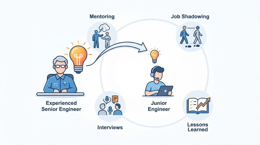
    Aging plants often come with an aging workforce. Experienced operators and maintenance staff know the quirks of the plant, the history of repairs, and the workarounds that keep it running. When they retire, that knowledge leaves with them. A life extension program should capture this knowledge through documented procedures, interviews, and training of newer staff. It should also make sure the skills needed for upgraded systems, such as modern control systems and condition monitoring, are available.

    Contracts, Permits, and Commercial Alignment

    Technical life must match commercial life. Before committing capital, confirm that the extended operating period is supported by:

    • Operating permits and licenses valid for the extended period.
    • Offtake or supply agreements (for example, power purchase agreements or product supply contracts) that run long enough to recover the investment.
    • Land, lease, and site rights that extend to the planned end date.
    • Insurance and financing terms consistent with the plan.

    A plant that is technically sound but has no contract or permit beyond the next few years may not justify major investment.

    Economic Analysis

    Life extension decisions should be based on economic analysis.

    Analysis elements:

    • Capital cost: What is the cost of the life extension work?
    • Operating cost: How will operating costs change?
    • Revenue: What revenue will the plant generate?
    • Remaining life: How long will the plant operate after extension?
    • Alternatives: What are the alternatives (replacement, shutdown)?
    • Risk: What are the risks, and how are they valued?

    Analysis methods:

    • Net present value (NPV): Present value of future cash flows minus investment.
    • Internal rate of return (IRR): The discount rate at which NPV equals zero; a measure of return on investment.
    • Payback period: Time to recover the investment. It is easy to understand but ignores the time value of money and what happens after payback.
    • Levelized cost of product: Cost per unit of output over the plant’s life. For power plants this is the levelized cost of electricity (LCOE).

    When comparing alternatives with different lives, such as extending for 10 years versus building a plant that lasts 30, use a method that puts them on a comparable basis, such as equivalent annual cost. Include the cost of outages, the cost of risk, and decommissioning costs in the comparison. The economic analysis should be honest and comprehensive. Optimistic assumptions can lead to poor decisions.

    Decision Framework: Extend, Partially Replace, Replace, or Retire

    Life extension is rarely a yes/no decision. A practical framework considers a range of options:

    Option When It Fits
    Extend as is, with maintenance optimization Condition is good and risks are manageable
    Targeted repair and replacement Most equipment is sound; specific items limit life
    Major refurbishment or rerate Core equipment is sound and added capacity or efficiency adds value
    Replace with a new plant or unit Condition, compliance, or technology makes extension uneconomic
    Mothball or retire Demand, economics, or safety no longer support operation

    Compare options on the same basis: cost, risk, performance, schedule, and what happens at the end. An exit plan for decommissioning, including cost and responsibilities, belongs in every option, because life extension only postpones that obligation, and a realistic end date makes the economics more honest.

    Common Mistakes in Life Extension

    Even experienced organizations make mistakes. Common ones include:

    • Deferring assessment: Waiting until problems occur.
    • Underestimating scope: Discovering more work than expected.
    • Underestimating cost: Budget overruns.
    • No contingency for discovery work: Treating inspection findings as a surprise instead of an expectation.
    • Ignoring obsolescence: Discovering too late that parts are unavailable.
    • Ignoring compliance: Discovering too late that regulations have changed.
    • Ignoring commercial limits: Investing in a plant whose permits, contracts, or site rights end soon.
    • Optimistic assumptions: Overestimating remaining life or revenue.
    • Poor records: Making decisions without reliable design, inspection, or repair data.
    • Treating safety as a side issue: Not revalidating hazards and safety systems after years of change.
    • Overlooking cybersecurity: Adding networked controls without protecting them.
    • Skipping MOC and PSSR: Making changes without proper review.
    • No plan: Performing work reactively instead of strategically.
    • No follow-through: Failing to complete planned work.

    These mistakes can turn a viable life extension into a failed program.

    How Japanese EPC Firms Approach Life Extension

    Japanese engineering firms are often noted for a disciplined approach to plant life extension. Common characteristics include:

    • Thorough assessment: Equipment condition and remaining life are assessed carefully.
    • Detailed planning: Life extension is planned as a program, not a series of projects.
    • Conservative assumptions: Remaining life and performance are typically estimated conservatively.
    • Comprehensive documentation: Assessment, planning, and execution are documented.
    • Disciplined execution: Work is performed as planned, with tight control.
    • Long-term focus: Life extension is treated as an investment in the plant’s future.

    For plant owners, this often means life extension programs that deliver the intended results.

    How to Evaluate Life Extension Readiness

    When considering life extension for your plant, ask:

    Question Why It Matters
    Has equipment condition been assessed? You cannot plan without knowing condition
    Has remaining life been estimated, and is it kept up to date? Determines how long the plant can operate
    Are design, inspection, and repair records reliable? Decisions depend on good data
    Has the design basis been compared with current codes? Identifies hidden compliance costs
    Have fitness-for-service and risk-based inspection been considered? Supports defensible decisions on degraded equipment
    Have hazard studies and safety systems been revalidated? Keeps risk acceptable as the plant ages
    Has obsolescence been reviewed? Identifies equipment at risk
    Is there a spare parts strategy? Prevents delays from long lead times
    Has compliance been reviewed? Identifies regulatory gaps
    Do permits, contracts, and site rights cover the extended life? Ensures investment can be recovered
    Is there a life extension plan? Provides a roadmap for the work
    Is the economic case sound, with alternatives compared fairly? Justifies the investment
    Is there an exit plan for decommissioning? Makes the economics realistic
    Are turnarounds planned to include life extension? Provides the opportunity to perform work
    Is knowledge being captured from experienced staff? Protects against loss of expertise
    Is there a process for monitoring and adjusting? Keeps the program on track

    A plant that addresses these questions is ready to plan and execute life extension.

    Key Takeaways

    • Life extension keeps aging plants operating safely, reliably, and economically beyond design life
    • The decision requires an honest assessment of both the plant and the business case
    • Design life is a starting assumption, not a hard limit; useful life depends on condition and operation
    • Key drivers of aging include physical degradation, obsolescence, regulatory changes, and loss of knowledge
    • Reliable records and a design basis and code gap review are the foundation of assessment
    • Remaining life assessment is the foundation of life extension planning, and it should feed directly into maintenance planning
    • Fitness-for-service assessment (for example, API 579) and risk-based inspection help focus effort and avoid unnecessary replacement
    • Plan life extension as a staged program; staging allows early exit if replacement is the better option
    • Strategies include maintenance optimization, repair, replacement, upgrade, and compliance upgrade, all under MOC and followed by PSSR
    • Turnarounds are often the best opportunity to perform life extension work
    • Obsolescence and compliance should be addressed proactively, including a spare parts strategy and cybersecurity for digital upgrades
    • Revalidate hazards and safety systems; life extension must keep risk acceptable
    • Technical life must be supported by permits, contracts, and site rights
    • Capture knowledge from experienced staff before it is lost
    • Economic analysis should be honest and comprehensive and include alternatives, risk, and end-of-life costs
    • Japanese EPC firms emphasize thorough assessment and disciplined planning

    Conclusion

    Plant life extension is a strategic decision that affects safety, reliability, cost, and compliance. For small to medium-scale industrial plants, it is often the main alternative to building a new plant.

    By assessing condition and remaining life, planning as a program, addressing obsolescence and compliance, and executing disciplined work, owners and operators can extend the life of their plants safely, reliably, and economically.

  • Plant Documentation and Knowledge Management: Key Practices for Industrial Plants

    Plant Documentation and Knowledge Management: Key Practices for Industrial Plants

    Every plant generates vast amounts of information: design drawings, operating procedures, maintenance records, inspection reports, safety analyses, vendor manuals, and equipment data. All of it is essential to safe, reliable, and efficient operation. Yet in many plants, this information is scattered, outdated, or inaccessible when it is needed most.

    Plant documentation and knowledge management is the discipline of capturing, organizing, and maintaining the information that the plant depends on. It ensures that the right information is available to the right people at the right time, whether they are operating the plant, maintaining equipment, responding to an emergency, or planning a turnaround.

    For small to medium-scale industrial plants, documentation and knowledge management are especially important because there is less redundancy and fewer people who hold critical knowledge in their heads. When an experienced operator or engineer leaves, their knowledge can leave with them, unless it has been documented and shared.

    This article covers the key practices in plant documentation and knowledge management, from document control to knowledge retention.

    What Is Plant Documentation and Knowledge Management?

    Plant documentation is the collection of documents that describe the plant, its systems, its operation, and its history. Knowledge management is the broader discipline of capturing, organizing, and sharing the knowledge that people hold, including the knowledge that is not written down.

    Together, they cover:

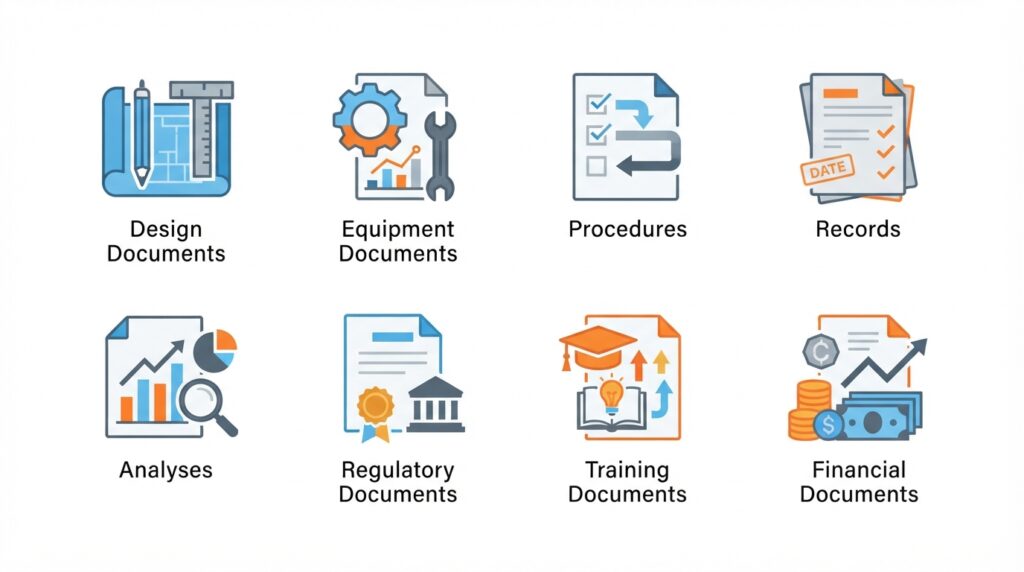
    • Technical documents: Drawings, datasheets, specifications
    • Procedures: Operating, maintenance, emergency, and safety procedures
    • Records: Maintenance history, inspection reports, test results
    • Analyses: Hazard analyses, risk assessments, incident investigations
    • Knowledge: Experience, lessons learned, troubleshooting expertise

    Documentation and knowledge management are not just administrative tasks. They are essential to safe and reliable operation.

    Why Documentation and Knowledge Management Matter

    Poor documentation and knowledge management lead to real problems.

    Factor Impact of Good Documentation Impact of Poor Documentation
    Safety Procedures and hazards are clear Operators work from memory or outdated information
    Reliability Maintenance history supports decisions Equipment history is lost; problems recur
    Efficiency Information is found quickly Time wasted searching for documents
    Compliance Records demonstrate compliance Fines and penalties for missing records
    Continuity Knowledge is retained when people leave Critical knowledge is lost
    Turnarounds Work packages are complete and accurate Rework and delays due to missing information
    Incident response Emergency information is accessible Response is slowed by missing information
    Modifications Current drawings support sound engineering Designs are based on assumptions that no longer match the plant

    For small plants, where fewer people hold critical knowledge, documentation and knowledge management are especially important.

    Types of Plant Documentation

    Plants generate many types of documentation.

    Category Examples
    Design documents P&IDs, PFDs, isometrics, electrical drawings, layout drawings, cause-and-effect diagrams
    Equipment documents Datasheets, vendor manuals, spare parts lists, certificates, warranties
    Procedures Operating procedures, maintenance procedures, emergency procedures
    Records Maintenance history, inspection reports, test results, calibration records
    Analyses HAZOP studies, risk assessments, incident investigations, MOC records
    Regulatory documents Permits, licenses, compliance reports, inspection certificates
    Training documents Training materials, competency records, qualification records
    Financial documents Budgets, cost records, contracts, purchase orders

    Each category has its own requirements for accuracy, currency, and retention.

    Documentation Begins During Design and Construction

    Documentation management should begin during design and construction, not after handover. Drawings, datasheets, and procedures created during the project should be organized and handed over in a usable form.

    In practice, this means the owner should:

    • Specify documentation requirements in the contract: Define the document types, formats, numbering scheme, and level of detail required from the EPC contractor and vendors.
    • Agree on a numbering and naming convention early: Retrofitting document numbers after handover is costly and error-prone.
    • Require as-built documentation: Drawings and datasheets should reflect what was actually built, not only what was designed.
    • Link documents to equipment: Tag numbers should tie drawings, datasheets, manuals, and spare parts lists together.
    • Review handover packages before acceptance: Check completeness and quality before final payment or project closeout, when the owner still has leverage.

    A well-organized handover package gives the plant a reliable documentation baseline from the first day of operation. A poor one forces the operating team to reconstruct information for years.

    Document Control

    Document control is the process of managing documents throughout their lifecycle, from creation to revision to archiving.

    Key elements of document control:

    • Unique identification: Every document has a unique number or identifier.
    • Version control: The current version is clearly identified; superseded versions are archived.
    • Approval: Documents are reviewed and approved before use.
    • Distribution: Controlled distribution ensures the right people have the right documents.
    • Revision management: Changes are tracked, approved, and communicated.
    • Access control: Documents are accessible to those who need them and protected from unauthorized changes.
    • Retention: Documents are retained for the required period.
    • Archiving: Superseded documents are archived, not discarded.

    Without document control, documents become outdated, inconsistent, and unreliable.

    The Role of the Document Controller

    In larger plants, a document controller is responsible for the document management system: issuing document numbers, tracking revisions, distributing documents, and maintaining the archive. In smaller plants, this role may be combined with other responsibilities, for example with those of a planner, administrator, or engineer.

    Regardless of plant size, the responsibilities should be clearly assigned to a named person. When document control is “everyone’s job,” it often becomes no one’s job.

    Document Retention

    Retention requirements vary by document type and jurisdiction. Regulatory documents and safety analyses are often retained for the life of the plant. Maintenance records may be retained for a defined period, such as 5 to 10 years. Some incident records have shorter minimum periods set by regulation, but many owners choose to keep them longer because of their value for learning and investigations. Retention requirements should be documented in a retention schedule.

    A retention schedule typically defines:

    • Document type: For example, P&IDs, inspection reports, training records.
    • Retention period: How long the document must be kept.
    • Basis: The regulation, standard, contract, or company policy that sets the requirement.
    • Responsible owner: Who decides when a document can be archived or disposed of.
    • Disposal method: How documents are destroyed or permanently archived when the retention period ends.

    Owners should confirm the requirements that apply in their jurisdiction with the relevant authorities or legal counsel.

    Document Management Systems

    A document management system (DMS) helps organize and control documents.

    Features of a good DMS:

    • Central repository: All documents in one place.
    • Search: Fast and accurate search by number, title, or content.
    • Version control: Automatic tracking of versions.
    • Access control: Permissions by user or role.
    • Workflow: Review and approval workflows.
    • Audit trail: Record of who accessed or changed documents.
    • Integration: Links to other systems (CMMS, ERP, etc.).
    • Backup: Regular backup and disaster recovery.

    For small plants, a simple DMS may be sufficient. Even a well-organized shared drive with clear naming conventions and folder structure can work, provided it is consistently maintained and access is controlled.

    Digital vs. Paper Documentation

    Many plants are transitioning from paper to digital documentation. Digital documentation offers advantages: searchability, accessibility, backup, and version control. However, paper documentation may still be required for field use, and critical documents should be available even during power or network outages.

    Practical considerations include:

    • Field access: Operators and maintenance staff need documents where the work is done. Tablets, ruggedized devices, or controlled paper copies may be needed, depending on the area.
    • Hazardous areas: Electronic devices used in classified areas must be suitably certified.
    • Controlled paper copies: Where paper is used, copies should be marked as controlled or uncontrolled, and a process should exist to replace them when revised.
    • Emergency access: Emergency procedures, key drawings, and contact lists should be available in a form that does not depend on the network.
    • Backup and cybersecurity: Digital archives need regular backups, offsite or separate copies, and protection against unauthorized access.
    • Format longevity: Long-lived documents should be stored in formats that will remain readable over the plant’s life.
    • Legacy documents: Scanning old paper drawings is a good start, but scanned files still need indexing and numbering to be searchable and useful.

    Keeping Documentation Current

    Documentation is only useful if it is current. Outdated documentation can be worse than no documentation because it creates false confidence.

    Common causes of outdated documentation:

    • Changes made without updating documents.
    • Documents updated but not distributed.
    • Multiple versions in circulation.
    • Documents created but never approved.
    • Documents not reviewed on schedule.

    Practices to keep documentation current:

    • Management of Change (MOC): Require document updates as part of MOC, and do not close out a change until the affected documents are revised.
    • Regular review: Review documents on a defined schedule.
    • Clear ownership: Assign responsibility for each document type.
    • Change control: Update documents as part of any change, including minor modifications and temporary changes.
    • Field verification: Periodically audit documents against actual plant conditions, for example by walking down P&IDs.
    • Redline process: Provide a simple way for operators and technicians to mark up discrepancies they find, and a process to incorporate those markups into the master documents.

    Document currency is a discipline, not a one-time effort.

    Procedures: The Foundation of Safe Operation

    Procedures are among the most important documents in a plant. They describe how to operate, maintain, and respond to emergencies.

    Procedure Type Purpose
    Operating procedures How to start up, operate, and shut down the plant
    Emergency procedures How to respond to emergencies
    Maintenance procedures How to inspect, maintain, and repair equipment
    Safety procedures Permit-to-work, lockout/tagout, confined space, hot work
    Alarm response procedures How to respond to specific alarms

    Key requirements for good procedures:

    • Accurate: Reflect actual plant configuration and operation.
    • Clear: Written in plain language, step-by-step.
    • Complete: Cover normal, abnormal, and emergency situations.
    • Current: Updated when changes occur.
    • Accessible: Available to those who need them.
    • Usable: Written for use in the field, not just for audits.

    Good procedures are usually developed with the people who perform the work. Operators and technicians should be involved in drafting and reviewing them, and procedures should be tested, for example through walk-throughs or simulator exercises, before being issued. Many regulatory frameworks for hazardous processes also expect operating procedures to be reviewed periodically, commonly at least annually, to confirm they remain current.

    Procedures that are not accurate or not used are worse than no procedures.

    Records and History

    Records document what has happened at the plant: maintenance, inspections, tests, incidents, and changes.

    Key records:

    • Maintenance history: What was done, when, by whom, and what was found.
    • Inspection records: Results of inspections and tests.
    • Calibration records: Instrument calibration and verification.
    • Incident records: What happened, why, and what was done.
    • Change records: MOC documentation and approvals.
    • Training records: Who was trained on what and when.

    Records support:

    • Decision-making: What has worked before? What failed?
    • Trend analysis: Is performance improving or degrading?
    • Compliance: Demonstrating compliance with regulations.
    • Investigations: Understanding what happened and why.
    • Planning: Scheduling maintenance and turnarounds.

    Records must be accurate, complete, and accessible. A record is only as valuable as the detail it contains: “repaired pump” tells the next reader little, while the failure mode, the findings, the parts replaced, and the as-left condition can inform future decisions.

    Knowledge Management

    Knowledge management goes beyond documents. It captures the experience, expertise, and insights that people hold.

    Type Description Example
    Explicit Knowledge that is documented Procedures, drawings, manuals
    Tacit Knowledge held by individuals Experience, judgment, troubleshooting skills
    Implicit Knowledge embedded in practices How things are actually done

    In practice, tacit and implicit knowledge overlap. Both are learned through experience and are rarely written down. Both are the most difficult to capture and the most at risk when people leave.

    Capturing Tacit Knowledge

    Capturing tacit knowledge in industrial plants

    Practices for capturing tacit knowledge:

    • Mentoring: Experienced staff work with less experienced staff.
    • Job shadowing: Junior staff observe experienced staff.
    • Interviews: Structured interviews to capture expertise.
    • Lessons learned: Capturing and sharing lessons from projects and incidents.
    • Communities of practice: Groups that share knowledge across the organization.
    • Documentation: Writing down what experienced staff know.
    • Training: Formal training that transfers knowledge.
    • Exit interviews: Capturing knowledge before people leave.

    Useful techniques include recording walk-through videos of complex tasks, annotating photos of equipment, and keeping troubleshooting logs that record symptoms, causes, and fixes. Short, practical formats are more likely to be created and used than long documents.

    For small plants, where there may be only one or two people with critical knowledge, capturing that knowledge is especially important.

    Knowledge Retention

    Knowledge retention is about keeping critical knowledge in the organization when people leave, retire, or change roles.

    Risks of knowledge loss:

    • Retirement: Experienced staff retire, taking decades of knowledge.
    • Turnover: Staff leave for other opportunities.
    • Promotion: Staff move to new roles, leaving gaps.
    • Reorganization: Roles change, and knowledge is not transferred.

    Strategies for knowledge retention:

    • Identify critical knowledge: What knowledge is essential and at risk? A simple review of critical roles and single points of failure is a good starting point.
    • Document what can be documented: Procedures, lessons learned, troubleshooting guides.
    • Transfer through people: Mentoring, shadowing, and training.
    • Build redundancy: More than one person knows critical tasks.
    • Plan for succession: Identify and prepare replacements.
    • Create a learning culture: Encourage knowledge sharing and make it part of normal work, not an extra task.
    • Start early: Begin transferring knowledge well before an expected departure.

    Knowledge retention is a long-term investment.

    Documentation and Knowledge in Turnarounds

    Turnarounds are times when documentation and knowledge are especially critical.

    Documentation needs during turnarounds:

    • Work packages: Complete and accurate.
    • Drawings: Current and accessible.
    • Procedures: Updated for the work being done.
    • Records: Inspection and test results documented.
    • As-builts: Updated after modifications.

    Knowledge needs during turnarounds:

    • Experienced staff: To supervise and troubleshoot.
    • Contractor knowledge: To perform specialized work.
    • Lessons from previous turnarounds: To avoid repeating mistakes.

    After the turnaround, findings, changes, and lessons learned should be captured and the documentation updated before the knowledge fades. Good documentation and knowledge management make turnarounds smoother and safer.

    Documentation and Knowledge in Emergencies

    In an emergency, documentation and knowledge must be immediately accessible.

    Documentation needs during emergencies:

    • Emergency procedures: Clear and accessible.
    • P&IDs: Current and available.
    • Safety data sheets (SDS): For hazardous materials.
    • Site maps: Showing access routes and assembly points.
    • Contact lists: For internal and external responders.

    Knowledge needs during emergencies:

    • Trained personnel: Who know what to do.
    • Emergency responders: Who know the plant.
    • Experience: From previous incidents and drills.

    In an emergency, there is no time to search for documents or ask questions. Everything must be ready, and some of it must be available without power or network access. Contact lists and site maps should be reviewed regularly, since out-of-date phone numbers are a common failure.

    Common Mistakes in Documentation and Knowledge Management

    Even experienced organizations make mistakes. Common ones include:

    • Outdated documents: Not updated after changes.
    • Multiple versions: Different versions in circulation.
    • Inaccessible documents: Hard to find when needed.
    • No document control: No version control or approval.
    • Incomplete records: Missing information.
    • Knowledge in silos: Knowledge held by individuals, not shared.
    • No succession planning: Knowledge lost when people leave.
    • No lessons learned: Mistakes repeated.
    • Documentation for audits only: Documents created for compliance, not for use.
    • Poor handover: Project documentation accepted without review and never organized.
    • No retention schedule: Documents discarded too early or kept indefinitely without a reason.
    • Over-reliance on a single system or person: No backup if the system fails or the person leaves.

    These mistakes lead to inefficiency, errors, and incidents.

    How Japanese EPC Firms Approach Documentation and Knowledge Management

    Japanese engineering firms are known for their disciplined approach to documentation. Common characteristics include:

    • Thorough documentation: Everything is documented, and documentation is maintained.
    • Document control: Version control and approval are strict.
    • Procedures: Procedures are clear, accurate, and followed.
    • Knowledge transfer: Experienced staff mentor junior staff.
    • Lessons learned: Lessons are captured and applied.
    • Long-term focus: Documentation and knowledge are treated as long-term assets.
    • Complete handover packages: Project documentation is organized and delivered in a form the operating team can use.

    For plant owners, this often means a plant where information is reliable, accessible, and useful.

    How to Evaluate Documentation and Knowledge Management

    When reviewing documentation and knowledge management, ask:

    Question Why It Matters
    Is there a document control system? Ensures documents are current and approved
    Is someone responsible for document control? Ensures accountability
    Were project documents handed over in a usable form? Provides a reliable baseline
    Are documents accessible, including in outages? Ensures information is available when needed
    Are documents current? Prevents errors from outdated information
    Is there a retention schedule? Ensures records are kept as long as required
    Are procedures accurate and used? Ensures safe and consistent operation
    Are records complete? Supports decisions, compliance, and investigations
    Is critical knowledge documented? Prevents knowledge loss
    Is knowledge shared? Builds organizational capability
    Is there succession planning? Prepares for departures
    Are lessons learned captured and applied? Prevents repeating mistakes

    A plant that addresses these questions is likely to have effective documentation and knowledge management.

    Conclusion

    Plant documentation and knowledge management are not administrative overhead. They are essential to safe, reliable, and efficient operation. For small to medium-scale industrial plants, where fewer people hold critical knowledge, they are especially important.

    By starting documentation management during design and construction, and by focusing on document control, procedures, records, knowledge capture, and knowledge retention, owners and operators can ensure that the plant’s information is reliable, accessible, and useful, today and in the future.

    Key Takeaways

    • Documentation and knowledge management ensure the right information is available when needed
    • Documentation management should begin during design and construction, not after handover
    • Document control manages documents through their lifecycle, and a named person should be responsible for it
    • Retention requirements vary by document type and jurisdiction and should be recorded in a retention schedule
    • Digital documentation improves searchability and control, but critical documents must remain available during power or network outages
    • Outdated documentation can be worse than no documentation
    • Procedures must be accurate, clear, complete, current, accessible, and usable
    • Records support decisions, compliance, and investigations
    • Knowledge management captures both explicit and tacit knowledge
    • Knowledge retention prevents critical knowledge from leaving with people
    • Japanese EPC firms emphasize thorough documentation and knowledge transfer
  • Plant Benchmarking: How to Measure and Improve Performance

    Plant Benchmarking: How to Measure and Improve Performance

    Every plant wants to know how it is performing. But performance numbers alone (availability, heat rate, maintenance cost) mean little without context. Is 92% availability good? Is a heat rate of 9,500 kJ/kWh competitive? Is maintenance cost per MW in line with similar plants?

    Benchmarking answers these questions. It compares your plant’s performance against internal targets, historical performance, industry standards, or similar plants. It shows where you are strong, where you are weak, and where improvement is possible.

    For small to medium-scale industrial plants, benchmarking is especially valuable because there are fewer resources to waste on the wrong priorities. It helps direct limited effort toward the areas with the greatest potential for improvement.

    This article covers the key concepts and practices of plant benchmarking, from what to measure to how to use the results.

    What Is Benchmarking?

    Benchmarking is the process of comparing your plant’s performance against a reference point to identify gaps and opportunities for improvement.

    The reference point can be:

    • Internal: Historical performance, other units in the same plant, best-performing shift
    • External: Similar plants, industry averages, best-in-class performers
    • Standards: Design values, regulatory requirements, manufacturer specifications
    • Targets: Goals set by management or corporate

    Benchmarking is not just measurement. It is about learning and improvement. The goal is not only to know where you stand, but to do something about it.

    Benchmarking also differs from simple performance monitoring. Monitoring tells you what a metric is today. Benchmarking tells you whether that value is good, why it differs from the reference, and what to do next.

    Why Benchmarking Matters

    Factor Impact of Benchmarking Impact of No Benchmarking
    Performance awareness Know where you stand Assume performance is acceptable
    Prioritization Focus on the biggest gaps Spread effort evenly or randomly
    Motivation Clear targets drive improvement No sense of urgency
    Accountability Performance is visible and tracked Performance is not managed
    Learning Learn from better performers Reinvent solutions others have found
    Credibility Data supports investment decisions Decisions based on opinion

    For small plants, benchmarking helps identify which improvements will have the greatest impact.

    What to Benchmark

    Category Typical Metrics
    Availability Availability factor, forced outage rate, equivalent availability
    Reliability MTBF, failure rate, unplanned outage frequency
    Efficiency Heat rate, thermal efficiency, fuel consumption
    Cost Maintenance cost per MW, O&M cost per MWh, total cost of ownership
    Safety Lost-time injury rate, recordable incident rate, near-miss reporting
    Environmental Emissions per MWh, water consumption, waste generation
    Maintenance PM compliance, backlog, wrench time, schedule adherence
    Spares Inventory turnover, stockout rate, obsolescence
    Staffing Staff per MW, overtime rate, training hours per employee

    Not every plant needs to benchmark everything. Start with the metrics that matter most for your plant’s objectives, typically a handful covering availability, efficiency, cost, and safety.

    Define Each Metric Precisely

    Two plants can report “availability” or “heat rate” and mean different things. Before comparing, agree on definitions and boundaries:

    • Availability: Is it availability factor, equivalent availability factor, or service factor? Are planned outages included or excluded? Many power-sector benchmarks follow standard definitions such as IEEE Std 762 and the NERC GADS data reporting conventions. Using them makes external comparison far easier.
    • Heat rate: Is it gross or net (after auxiliary power)? Is it based on lower heating value (LHV) or higher heating value (HHV)? The difference is several percent for natural gas, enough to hide or create an apparent gap.
    • Maintenance cost: Does it include labor, contractors, materials, and major overhauls? Does it include capital projects or only expensed work?
    • Staffing: Does it include contractors, security, and administration?

    Document each definition once and apply it consistently. A benchmark with unclear definitions is worse than none because it can point effort in the wrong direction.

    Leading vs. Lagging Indicators

    Benchmarks fall into two groups.

    • Lagging indicators measure what has already happened. Examples: forced outage rate, availability, lost-time injury rate, maintenance cost per MWh. They confirm results but arrive too late to prevent them.
    • Leading indicators predict future performance. Examples: PM compliance, maintenance backlog, near-miss reporting, training hours, condition-monitoring alert response time. They show whether the conditions for good performance are in place.
    Type Examples Strength Limitation
    Lagging Forced outage rate, availability, injury rate, heat rate Objective measure of results Reports problems after they occur
    Leading PM compliance, backlog, near-miss reports, training hours Allows early action Link to results must be validated

    A balanced set of both provides a fuller picture. For example, a falling PM compliance rate (leading) often precedes a rise in forced outages (lagging). Tracking only lagging indicators means you learn about problems after they have cost you money.

    Types of Benchmarking

    Types of benchmarking for industrial plants

    Type Description Example
    Internal Comparing within your own organization Unit 1 vs. Unit 2; Shift A vs. Shift B
    Competitive Comparing against direct competitors or similar plants Your plant vs. a similar plant nearby
    Functional Comparing similar functions across industries Your maintenance vs. best-in-class maintenance
    Generic Comparing processes against world-class performance regardless of industry Your safety management vs. the best safety performers anywhere
    Historical Comparing against your own past performance This year vs. last year

    Historical benchmarking is technically a form of internal benchmarking, but it is listed separately because it is so widely used. For most small plants, internal and historical benchmarking are the easiest to start with. Competitive and functional benchmarking require access to external data.

    Setting the Reference Point

    The reference point determines what “good” looks like.

    Reference Point Description When to Use
    Design value What the plant was designed to achieve When design data is reliable; adjust for age and degradation
    Historical best Your best performance in the past To identify what is achievable
    Industry average Typical performance for similar plants To gauge competitiveness
    Best-in-class The best performance achieved by any plant To set aspirational targets
    Regulatory minimum Minimum required by law or permit To ensure compliance
    Management target Goal set by management To align with business objectives

    Using multiple reference points provides a fuller picture. Comparing against both industry average and best-in-class shows where you stand and where you could be. Be cautious with design values on older plants: equipment degrades, so a plant that is 20 years old may never return to its original heat rate, and a gap to design may not be recoverable.

    Data Collection and Quality

    Benchmarking depends on good data. Poor data leads to wrong conclusions.

    Data quality requirements:

    • Accuracy: Data reflects actual performance.
    • Completeness: All relevant data is captured.
    • Consistency: Data is collected the same way over time.
    • Timeliness: Data is available when needed.
    • Traceability: Data can be traced to its source.

    Data sources:

    • Control systems/historian: Operating data, performance trends
    • CMMS: Maintenance records, work orders, costs
    • Production records: Output, downtime, quality
    • Safety records: Incidents, near-misses, training
    • Financial records: Costs, budgets, expenditures

    Data should be validated before use. Check instrument calibration for key measurements such as fuel flow and generator output, since a small meter error can create a false efficiency gap. A common mistake is to benchmark against data that is incomplete or inconsistent, such as a CMMS in which work orders are not closed out or costs are not charged to the right equipment.

    Normalizing Data for Comparison

    Plants differ in size, age, technology, and operating conditions. To compare fairly, data must be normalized.

    Common normalization factors:

    • Per MW: Cost or consumption per megawatt of installed capacity.
    • Per MWh: Cost or consumption per megawatt-hour of output.
    • Per operating hour: Cost or consumption per hour of operation.
    • Per unit of production: Cost or consumption per unit of product.
    • Capacity factor: Actual output as a percentage of the output possible at full rated capacity over the same period. It is often used to group plants with similar operating patterns, since baseload and peaking plants should not be compared directly.
    • Ambient and fuel corrections: Performance corrected to reference conditions for temperature, altitude, humidity, and fuel quality.

    Without normalization, comparisons can be misleading. A plant with twice the capacity will have higher absolute costs but may be more efficient per MW. Likewise, a gas turbine running at partial load or in hot weather will show a worse heat rate than the same machine at full load on a cool day, even though nothing is wrong.

    Internal Benchmarking

    Internal benchmarking compares performance within your own organization.

    Examples:

    • Unit-to-unit: How does Unit 1 compare to Unit 2?
    • Shift-to-shift: How does Shift A compare to Shift B?
    • Year-to-year: How does this year compare to last year?
    • Department-to-department: How does maintenance compare to operations?

    Internal benchmarking is often the easiest place to start because the data is already available and the comparison is fair.

    Benefits:

    • No external data required.
    • Directly comparable.
    • Identifies internal best practices.
    • Builds healthy internal competition and motivation.

    Limitation: It can only show you the best you already do. If the whole plant is below industry standards, internal benchmarking will not reveal it.

    External Benchmarking

    External benchmarking compares your performance against other plants.

    Sources of external data:

    • Industry associations: Many industries publish benchmarking data.
    • Consultants: Firms that specialize in benchmarking.
    • Peer networks: Groups of plants that share data.
    • Published studies: Research and industry reports.
    • Equipment vendors and OEM user groups: Performance data from similar installations.

    Challenges:

    • Data may not be directly comparable.
    • Confidentiality concerns.
    • Cost of access.
    • Different definitions and boundaries.

    External benchmarking requires careful interpretation. Differences in plant age, technology, fuel, and operating conditions must be considered.

    If you exchange data directly with competitors, take care with commercially sensitive information such as pricing, contract terms, and future plans. Competition law in many jurisdictions restricts such exchanges. Use a neutral third party (an association or consultant) to aggregate and anonymize data, and obtain legal advice where in doubt.

    The Value of Peer Networks

    Peer networks (formal or informal groups of similar plants) can provide benchmarking data that is more relevant than broad industry averages. Many industries have established peer groups that share performance data confidentially. For small plants, a peer group of five to ten similar facilities often yields more useful comparisons than a large database dominated by plants of a different size or technology. Peer groups also provide something a database cannot: the chance to ask the better performer how they achieved their results.

    Analyzing Gaps

    The purpose of benchmarking is to identify gaps and understand why they exist.

    Gap analysis questions:

    • Where are we significantly better or worse than the reference?
    • Why is the gap there? What causes it?
    • Is the gap due to design, operation, maintenance, or external factors?
    • What would it take to close the gap?
    • Is closing the gap worth the investment?

    Not all gaps need to be closed. Some are due to factors outside your control, such as plant age, location, or fuel quality. Focus on gaps that are both significant and addressable.

    Worked Example

    A 50 MW net plant operates at a 70% capacity factor. Its net heat rate (LHV basis) is 9,500 kJ/kWh. A peer-group benchmark for similar plants, on the same basis and corrected to the same conditions, is 9,000 kJ/kWh.

    • Efficiency: 3,600 ÷ 9,500 = 37.9% versus 3,600 ÷ 9,000 = 40.0%.
    • Gap: 500 kJ/kWh, or about 5.6% more fuel per kWh.
    • Annual output: 50 MW × 8,760 h × 0.70 = 306,600 MWh.
    • Excess fuel energy: 306,600,000 kWh × 500 kJ/kWh ≈ 153,300 GJ per year.
    • Cost: At an assumed fuel price of USD 8 per GJ, the gap is worth about USD 1.2 million per year.

    That figure tells the plant how much it can reasonably spend to investigate and close the gap, for example on condenser or heat exchanger cleaning, turbine inspection, instrument calibration, or operating-mode changes. Part of the gap may be unrecoverable (age, design), so the investigation should separate the recoverable portion from the rest.

    A similar view applies to availability. The difference between 92% and 95% availability is 3 percentage points, or about 263 hours per year of additional generation capability.

    Using Benchmarking Results

    Benchmarking continuous improvement cycle for industrial plants

    Benchmarking is only valuable if it leads to action.

    Steps to use benchmarking results:

    1. Identify the biggest gaps: Where is performance significantly below the reference?
    2. Investigate causes: Why is the gap there?
    3. Prioritize opportunities: Which gaps offer the greatest improvement potential for the effort?
    4. Set improvement targets: What performance is achievable, and by when?
    5. Develop action plans: What changes are needed, who owns them, and what do they cost?
    6. Implement and monitor: Track progress and adjust as needed.

    Benchmarking should be part of a continuous improvement cycle, not a one-time study.

    Benchmarking Frequency

    Benchmarking frequency depends on the metric and the rate of change. Some metrics, such as safety and availability, are reviewed monthly or quarterly. Others, such as heat rate and maintenance cost, are typically benchmarked formally once a year, although heat rate is often trended monthly through performance monitoring so that degradation is caught early. The key is consistency: benchmark at the same interval each time, using the same definitions, so that results are comparable.

    Metric Type Typical Review Interval
    Safety, near-miss reporting Monthly
    Availability, forced outage rate Monthly or quarterly
    PM compliance, backlog Monthly
    Heat rate / efficiency Monthly trending; annual formal benchmark
    Maintenance and O&M cost Quarterly trending; annual formal benchmark
    Staffing, spares performance Annually
    External benchmark study Annually or every two to three years

    Communicating Benchmark Results

    Benchmarking results can be sensitive. They should be communicated carefully. The purpose is improvement, not blame. Sharing results transparently, along with the plan to address gaps, builds trust and motivation. Present gaps as opportunities, credit teams that perform well, and keep the presentation simple: a one-page dashboard showing each key metric, its reference, the gap, and the action under way is usually more effective than a long report. People who feel that benchmarking is being used to judge them will tend to hide problems or manipulate data, which defeats the purpose.

    Common Pitfalls in Benchmarking

    Even experienced organizations make mistakes. Common ones include:

    • Comparing apples to oranges: Plants with different sizes, ages, technologies, or definitions.
    • Using poor data: Incomplete or inconsistent data leads to wrong conclusions.
    • Focusing only on numbers: Missing the context and causes behind the numbers.
    • Not normalizing: Comparing absolute values without adjusting for size or operating conditions.
    • Making excuses: Attributing every gap to factors outside your control without testing the assumption.
    • No follow-through: Benchmarking without action.
    • Benchmarking too much: Trying to measure everything instead of what matters.
    • Benchmarking too little: Tracking only one or two metrics, or only lagging indicators, and missing important problems.
    • Chasing the metric: Optimizing the number rather than the performance, for example deferring maintenance to meet a cost target.
    • Inconsistent intervals or definitions: Changing the method from year to year so trends cannot be trusted.

    These pitfalls reduce the value of benchmarking and can lead to wrong decisions.

    Benchmarking in Small Plants

    Small plants face particular challenges with benchmarking.

    Challenges:

    • Limited data.
    • Fewer resources for benchmarking.
    • Less access to external data.
    • Difficulty finding comparable plants.

    Practical approaches:

    • Start with internal benchmarking: Compare units, shifts, or years.
    • Focus on a few key metrics: For example availability, heat rate, maintenance cost, and safety, with one or two leading indicators.
    • Use industry associations: Many provide benchmarking data for their members.
    • Join peer networks: Share data with similar plants.
    • Use simple tools: Spreadsheets are often sufficient.
    • Build a baseline: Establish your own historical performance as a reference.
    • Improve incrementally: Small improvements add up.

    Small plants can benefit from benchmarking without a large investment.

    A Practical Starting Plan

    1. Month 1: Choose five to eight metrics, write down their definitions, and assign an owner for each.
    2. Month 2: Collect two to three years of historical data and validate it. Calculate your baseline.
    3. Month 3: Find at least one external reference (association data, peer group, or vendor data) and compare on a normalized basis.
    4. Month 4: Analyze the largest gaps, estimate their value, and select two or three for action.
    5. Ongoing: Review monthly or quarterly, repeat the full benchmark annually, and update targets as performance improves.

    Benchmarking and Continuous Improvement

    Benchmarking is most effective as part of a continuous improvement cycle.

    The cycle:

    1. Measure: Collect performance data.
    2. Compare: Benchmark against reference points.
    3. Analyze: Identify gaps and their causes.
    4. Improve: Implement changes to close gaps.
    5. Monitor: Track progress and verify improvement.
    6. Repeat: Continue the cycle.

    Each cycle should lead to measurable improvement. Over time, the plant’s performance improves and the reference points may need to be updated.

    How Japanese EPC Firms Approach Benchmarking

    Japanese engineering firms are known for their disciplined approach to performance management. Common characteristics include:

    • Systematic measurement: Performance is measured consistently and accurately.
    • Clear targets: Targets are set based on benchmarks and objectives.
    • Detailed analysis: Gaps are investigated thoroughly.
    • Disciplined execution: Improvement plans are implemented consistently.
    • Continuous improvement: Benchmarking is part of an ongoing cycle, in the spirit of kaizen.
    • Long-term focus: Improvement is sustained over time.

    For plant owners, this often means plants that continuously improve and remain competitive.

    How to Evaluate Benchmarking Readiness

    Question Why It Matters
    Are key metrics defined? You cannot benchmark what you do not measure
    Are definitions and boundaries documented? Ensures like-for-like comparison
    Is data accurate and consistent? Poor data leads to wrong conclusions
    Is data normalized for comparison? Ensures fair comparison
    Is there a mix of leading and lagging indicators? Gives early warning as well as results
    Is there a reference point? Defines what “good” looks like
    Is there a process for analyzing gaps? Turns data into insight
    Are results communicated constructively? Builds trust and encourages honest data
    Is there follow-through on findings? Benchmarking without action is wasted effort
    Is benchmarking part of continuous improvement? Sustains improvement over time

    A plant that addresses these questions is ready to benefit from benchmarking.

    Conclusion

    Benchmarking provides context for performance and direction for improvement. It helps plants understand where they stand, identify gaps, and focus effort where it matters most.

    For small to medium-scale industrial plants, benchmarking is especially valuable because resources are limited. By measuring key metrics, comparing against meaningful references, analyzing gaps, and taking action, plants can improve performance and remain competitive.

    Key Takeaways

    • Benchmarking compares performance against a reference point to identify gaps.
    • What to benchmark includes availability, reliability, efficiency, cost, safety, environmental, maintenance, spares, and staffing.
    • Types include internal, competitive, functional, generic, and historical.
    • Define metrics precisely (for example gross vs. net, LHV vs. HHV) so comparisons are like for like.
    • Data must be accurate, consistent, and normalized for fair comparison.
    • Use a balance of lagging indicators (results) and leading indicators (predictors).
    • Peer networks often provide more relevant data than broad industry averages.
    • Gap analysis identifies where performance is below the reference and why.
    • Benchmark at consistent intervals, and communicate results constructively, for improvement and not blame.
    • Benchmarking is only valuable if it leads to action, as part of a continuous improvement cycle.
    • Japanese EPC firms emphasize systematic measurement and disciplined execution.
  • Plant Reliability Engineering: Key Concepts and Practices

    Plant Reliability Engineering: Key Concepts and Practices

    Reliability is not an accident. It is the result of deliberate design, disciplined maintenance, and continuous improvement. Plants that operate reliably for decades do so because reliability was engineered into them, not because they were lucky.

    Reliability engineering is the discipline of understanding why equipment fails and applying that knowledge to prevent failures. It combines design, maintenance, operations, and data analysis into a single approach focused on keeping the plant available, efficient, and safe.

    For small to medium-scale industrial plants, reliability engineering is especially valuable because there is less redundancy and fewer resources to absorb failures. A reliability-focused approach helps direct limited resources where they have the greatest impact.

    This article covers the key concepts and practices of plant reliability engineering, from basic definitions to practical implementation.

    What Is Plant Reliability?

    Reliability is the probability that equipment or a system will perform its intended function without failure for a specified period under specified conditions.

    In practical terms, reliability means:

    • Equipment works when needed.
    • Equipment works as designed.
    • Equipment continues to work over time.
    • Equipment works safely.

    Reliability is not the same as availability, although the two are related.

    Term Definition Example
    Reliability Probability of performing without failure over a period 90% probability of running 8,000 hours without failure
    Availability Percentage of time equipment is available for operation 95% available over a year
    Maintainability Ease and speed of restoring equipment after failure Average repair time of 4 hours
    Relationship Availability depends on both reliability and maintainability High reliability and fast repair give high availability

    Availability depends on both how often equipment fails (reliability) and how quickly it is restored (maintainability). A pump that fails rarely but takes three weeks to repair can have worse availability than one that fails more often but is fixed in hours.

    Why Reliability Engineering Matters

    Reliability directly affects plant performance.

    Factor Impact of High Reliability Impact of Low Reliability
    Production Consistent output; commitments met Unplanned outages; lost production
    Cost Predictable maintenance; lower emergency costs High repair costs; premium purchases
    Safety Fewer failures; fewer incidents Failures create safety hazards
    Efficiency Equipment performs as designed Degraded performance; higher fuel cost
    Reputation Customer confidence maintained Lost customers; damaged reputation
    Morale Team pride in a reliable plant Firefighting culture; burnout

    Unplanned failures are also usually the most expensive kind. They bring lost production, expedited parts, overtime labor, and often collateral damage to other equipment. For small plants, where redundancy is limited, reliability is not optional. It is essential.

    Key Reliability Concepts

    Reliability engineering uses several fundamental concepts.

    Concept Definition Application
    Failure rate Frequency of failure over time Predicts how often equipment will fail
    MTBF Mean time between failures (repairable equipment) Average operating time between failures
    MTTF Mean time to failure (non-repairable items) Expected life of items replaced rather than repaired
    MTTR Mean time to repair Average time to restore equipment
    Inherent availability MTBF ÷ (MTBF + MTTR) Percentage of time equipment is available, excluding planned maintenance
    Failure mode How equipment fails Identifies how failures occur
    Root cause Fundamental reason for failure Prevents recurrence
    Bathtub curve Failure pattern over equipment life Guides maintenance strategy

    Worked example. A feed pump has an MTBF of 2,000 hours and an MTTR of 4 hours. Its inherent availability is 2,000 ÷ 2,004, or about 99.8%. If repairs took 40 hours instead, availability would drop to about 98.0%. This shows how much repair time matters.

    A common misunderstanding. MTBF is not the expected service life of equipment. If failures occur randomly at a constant rate, only about 37% of units will still be running after operating for a period equal to the MTBF. MTBF is a statistical average across a population, not a guarantee for an individual machine.

    The Bathtub Curve

    Bathtub curve for equipment reliability in industrial plants

    The bathtub curve describes one common failure pattern over an equipment’s life.

    Phase Failure Pattern Causes Maintenance Strategy
    Early life (infant mortality) High failure rate, decreasing Manufacturing defects, installation errors Commissioning, burn-in, quality control
    Useful life Low, roughly constant failure rate Random failures Condition monitoring and condition-based tasks
    Wear-out Increasing failure rate Aging, wear, fatigue Overhaul, replacement, increased monitoring

    Understanding where equipment is on the curve helps select the right maintenance strategy.

    An important caveat. The bathtub curve is a useful model, but it is not universal. Studies of failure patterns, most notably the aviation work behind reliability-centered maintenance, found that only a minority of components follow it. Many show infant mortality followed by a long, flat, random-failure period with no clear wear-out. For equipment with random failures, time-based overhauls do not reduce failures and can even introduce new ones through maintenance-induced errors. This is why condition-based approaches and failure data analysis matter.

    Reliability vs. Maintenance

    Reliability and maintenance are related but distinct.

    Aspect Reliability Engineering Maintenance
    Focus Preventing and reducing failures through design, analysis, and improvement Preserving equipment function and restoring it when it is lost
    Timing Design, operation, and after failures (to prevent recurrence) Scheduled, condition-based, and after failure
    Approach Analysis, design change, and improvement Inspection, servicing, repair, and replacement
    Goal Eliminate or reduce failures Keep equipment in service and minimize downtime
    Discipline Reliability engineering Maintenance management

    Reliability engineering asks, “How do we prevent this failure?” Maintenance asks, “How do we keep this equipment working, and how do we fix it quickly when it stops?” Both are necessary, but reliability addresses the root of the problem.

    Reliability Engineering Activities

    Reliability engineering involves several core activities.

    Activity Purpose When Applied
    Reliability prediction Estimate failure rates and reliability During design
    Reliability block diagrams Model system reliability and identify weak points During design and modification
    Criticality analysis Rank equipment by consequence of failure Design and operation
    FMEA Identify failure modes and effects During design and operation
    RCM Determine maintenance requirements Design and operation
    RCA Investigate failures and prevent recurrence After failures
    Condition monitoring Detect developing failures During operation
    Reliability testing Verify reliability through testing During design and commissioning
    Data analysis Track and analyze failure data Continuously
    Reliability improvement Implement changes to improve reliability Continuously

    These activities work together to build and maintain reliability.

    Reliability Block Diagrams (RBD)

    Reliability block diagrams (RBDs) model how components are arranged in a system, in series, parallel, or a combination, to calculate overall system reliability. They help identify where redundancy improves reliability and where single points of failure exist.

    • Series arrangement: All components must work for the system to work. System reliability is the product of component reliabilities. Two pumps in series, each with a reliability of 0.95, give a system reliability of 0.95 × 0.95 = 0.9025.
    • Parallel arrangement: The system works if at least one component works. Two parallel pumps, each with a reliability of 0.95, give a system reliability of 1 − (0.05 × 0.05) = 0.9975.

    The comparison shows two things. In a series arrangement, every added component lowers system reliability. In a parallel arrangement, redundancy raises it substantially. RBDs also reveal that a highly reliable redundant pair can still be undermined by a shared, single-point component such as a common suction header, a shared power supply, or a single control system. Simple RBD calculations assume independent failures. Common-cause failures, such as a shared utility loss, can defeat redundancy and should be considered separately.

    Criticality Analysis

    Criticality analysis ranks equipment by the consequences of failure: safety, environmental, production, and cost. It helps direct reliability resources to the equipment that matters most.

    A simple approach scores each asset for the severity of failure consequences and the likelihood of failure, then ranks assets by the combined score. Equipment is often grouped into categories such as:

    • Critical: Failure threatens safety, the environment, or production. These assets receive the full set of reliability practices, including FMEA, condition monitoring, and critical spares.
    • Important: Failure causes significant but manageable impact. These assets receive planned preventive and predictive tasks.
    • Standard: Failure has limited consequences. These assets may be run to failure or maintained at low cost.

    For small plants, criticality analysis is often the single most valuable first step, because it focuses limited effort where it counts.

    Reliability in Design

    Reliability starts with design. The choices made during design determine the reliability the plant can achieve.

    Design for reliability principles:

    • Simplicity: Fewer components mean fewer failure points.
    • Redundancy: Backup equipment for critical functions. Redundancy improves reliability but adds cost, complexity, and its own failure modes (such as standby equipment that fails to start), so it should be applied selectively.
    • Derating: Operating equipment below maximum ratings extends life.
    • Material selection: Materials suited to the operating environment.
    • Standardization: Common components reduce variety and simplify maintenance and spares.
    • Accessibility: Equipment accessible for inspection and maintenance.
    • Design margins: Adequate margin for uncertainty and variability.
    • Fault tolerance and fail-safe design: Systems that fail to a safe state and tolerate single faults.

    Reliability cannot be fully added after design. It must be designed in. Reliability can be improved later through modifications, but at greater cost and with less effect.

    Reliability in Operation

    Once the plant is operating, reliability depends on how it is operated and maintained.

    Operational factors:

    • Operating within design limits: Avoiding conditions outside the design envelope.
    • Proper startup and shutdown: Following procedures to minimize stress.
    • Load management: Avoiding rapid load changes that stress equipment.
    • Monitoring: Watching for signs of degradation.
    • Feedback: Reporting problems before they become failures.
    • Operator care: Routine rounds, cleanliness, lubrication checks, and early reporting of abnormal sounds, leaks, or vibration.

    Maintenance factors:

    • Preventive maintenance: Performing scheduled tasks.
    • Predictive maintenance: Monitoring condition and acting on findings.
    • Corrective maintenance: Repairing failures promptly and correctly.
    • Spare parts: Having the right parts when needed.
    • Documentation: Maintaining records that support analysis.
    • Quality of work: Correct procedures, torque values, alignment, and cleanliness, since poor workmanship is itself a common cause of failure.

    Operation and maintenance determine whether the design reliability is achieved in practice.

    Condition Monitoring and Predictive Maintenance

    Condition monitoring is a key reliability practice. It detects developing failures before they cause equipment to stop.

    Common monitoring techniques:

    Technique Detects Application
    Vibration analysis Bearing wear, imbalance, misalignment Rotating equipment
    Thermography Hot spots, loose connections, overheating Electrical panels, bearings
    Oil analysis Wear particles, contamination Gearboxes, engines, turbines
    Ultrasonic testing Leaks, thickness loss, bearing defects Piping, tanks, vessels
    Performance monitoring Efficiency loss, fouling Heat exchangers, compressors
    Motor current analysis Motor and driven equipment faults Motors, pumps, compressors
    Partial discharge testing Insulation deterioration Transformers, switchgear, medium- and high-voltage motors and cables
    Dissolved gas analysis Internal transformer faults Oil-filled transformers

    Electrical equipment. Electrical equipment, such as motors, transformers, and switchgear, also benefits from condition monitoring. Partial discharge testing, infrared thermography, and motor current analysis detect developing faults before they cause failure.

    The P-F interval. Condition monitoring works because most failures do not happen instantly. The point at which a developing problem becomes detectable (P) comes before functional failure (F). The time between the two is the P-F interval. Monitoring must be performed more often than the P-F interval, with enough warning time left to plan the repair. A vibration check every six months is of little use for a bearing whose P-F interval is a few weeks.

    Condition monitoring allows maintenance to be performed when needed, not on a fixed schedule.

    Reliability Data and Analysis

    Reliability engineering depends on data.

    Data sources:

    • Failure records: What failed, when, and why.
    • Maintenance records: What was done, when, and by whom.
    • Operating data: How equipment was operated.
    • Condition monitoring data: Trends and anomalies.
    • Design data: Specifications and expected performance.

    Analysis methods:

    • Failure rate analysis: How often does equipment fail?
    • Trend analysis: Is reliability improving or degrading?
    • Pareto analysis: Which failures cause the most problems? Often a small number of equipment items or failure modes account for most of the lost production.
    • Weibull analysis: What is the failure pattern? The Weibull shape parameter (β) indicates the pattern: β below 1 suggests early-life failures, β near 1 suggests random failures, and β above 1 suggests wear-out.
    • Root cause analysis: Why did the failure occur?

    Good data starts with consistent failure coding in the maintenance system. If work orders record only “repaired pump,” there is nothing to analyze. Recording the equipment, failure mode, cause, and downtime makes later analysis possible.

    Data without analysis is just records. Analysis turns data into insight.

    Reliability Metrics

    Key reliability metrics for industrial plants

    Reliability is measured with several key metrics.

    Metric Definition Target
    MTBF Mean time between failures Increasing over time
    MTTR Mean time to repair Decreasing over time
    Availability Percentage of time available 95%+ for most plants (varies by plant type)
    Reliability Probability of performing without failure Application-specific
    Failure rate Failures per unit time Decreasing over time
    OEE Overall equipment effectiveness (availability × performance × quality) 85%+ for world-class

    Metrics should be tracked over time to identify trends and improvement opportunities. They should also be applied to defined equipment groups, since a plant-wide average can hide a few chronic bad actors.

    Reliability Improvement

    Reliability is not static. It must be continuously improved.

    Improvement approaches:

    • Root cause analysis: Investigate failures and prevent recurrence.
    • FMEA: Identify failure modes and address them.
    • RCM: Optimize maintenance based on failure modes.
    • Reliability-centered design: Apply reliability principles to modifications.
    • Benchmarking: Compare against similar plants.
    • Best practices: Apply proven practices from industry.
    • Training: Build reliability skills in the team.
    • Culture: Make reliability a core value.

    Reliability-Centered Design for Modifications

    When equipment is modified or replaced, reliability principles should be applied to the new design. A modification that solves one problem but introduces another is not an improvement.

    In practice, this means:

    • Reviewing the failure history that prompted the change, so the modification targets the root cause rather than a symptom.
    • Applying a management of change (MOC) process so that effects on other equipment, operating procedures, and safety systems are assessed.
    • Considering maintainability, spares, and standardization for the new equipment, not just performance.
    • Updating drawings, procedures, and maintenance plans, and verifying the result after the change.

    Reliability improvement is a journey, not a destination.

    Building a Reliability Culture

    Reliability is not just a technical discipline. It is a culture.

    Elements of a reliability culture:

    • Leadership commitment: Reliability is a priority, not just a slogan.
    • Data-driven decisions: Decisions based on evidence, not opinion.
    • Proactive mindset: Fixing problems before they cause failures.
    • Continuous learning: Capturing and applying lessons.
    • Accountability: Everyone owns reliability in their area.
    • Collaboration: Operations, maintenance, and engineering work together.
    • Patience: Reliability improvements take time.

    A reliability culture is what sustains reliability over the long term.

    Reliability in Small Plants

    Small plants face particular challenges with reliability.

    Challenges:

    • Fewer resources for reliability programs.
    • Limited data for analysis.
    • Less specialist expertise.
    • Competing priorities.

    Practical approaches:

    • Focus on critical equipment: Use criticality analysis to apply reliability practices where they matter most.
    • Use simple tools: MTBF, MTTR, and failure tracking provide value without complexity.
    • Start with RCA: Investigate significant failures and prevent recurrence.
    • Use condition monitoring selectively: Apply it to critical rotating and electrical equipment.
    • Build skills gradually: Train the team on reliability basics.
    • Learn from others: Apply lessons from similar plants and from equipment suppliers.
    • Make it a habit: Reliability practices become routine over time.

    A practical starting sequence is: (1) rank equipment by criticality, (2) set up consistent failure recording, (3) track MTBF, MTTR, and downtime for critical equipment, (4) perform RCA on significant failures, (5) add condition monitoring where it is most valuable, and (6) review results regularly and expand gradually.

    Small plants can achieve high reliability with focused effort and simple tools.

    Common Mistakes in Reliability Engineering

    Even experienced organizations make mistakes. Common ones include:

    • Focusing on maintenance only: Reliability starts with design.
    • Reacting instead of preventing: Firefighting culture instead of proactive reliability.
    • Ignoring data: Making decisions without evidence.
    • Skipping RCA: Fixing symptoms instead of causes.
    • No metrics: Not measuring reliability or tracking improvement.
    • Over-maintaining: Performing unnecessary tasks, which wastes resources and can introduce errors.
    • Under-maintaining: Skipping needed tasks.
    • Treating all equipment equally: Failing to prioritize by criticality.
    • Misreading MTBF: Treating it as guaranteed life rather than a statistical average.
    • No culture: Reliability treated as a project, not a value.

    These mistakes keep plants in a cycle of failures and repairs.

    How Japanese EPC Firms Approach Reliability

    Japanese engineering firms are known for their disciplined approach to reliability. Common characteristics include:

    • Design for reliability: Reliability is designed in from the start.
    • Thorough documentation: Records support analysis and improvement.
    • Disciplined maintenance: Procedures are followed consistently.
    • Continuous improvement: Lessons are captured and applied.
    • Long-term focus: Reliability is a long-term commitment, not a short-term goal.
    • Culture: Reliability is embedded in how people work.

    For plant owners, this often means plants that perform reliably for decades.

    How to Evaluate Reliability Readiness

    When reviewing reliability for your plant, ask:

    Question Why It Matters
    Is reliability a design priority? Reliability starts with design
    Has criticality analysis been performed? Focuses effort on the equipment that matters most
    Are reliability metrics tracked? What gets measured gets improved
    Is condition monitoring in place for rotating and electrical equipment? Detects problems before failures
    Is RCA performed for significant failures? Prevents recurrence
    Is FMEA applied to critical equipment? Identifies failure modes proactively
    Is RCM used to optimize maintenance? Directs effort where it matters
    Are single points of failure identified? RBDs reveal where redundancy is needed
    Are modifications reviewed for reliability impact? Prevents new problems from being introduced
    Is there a reliability culture? Sustains reliability over time
    Is there continuous improvement? Keeps reliability from degrading

    A plant that addresses these questions is likely to achieve high reliability.

    Conclusion

    Reliability engineering is the discipline of understanding why equipment fails and applying that knowledge to prevent failures. It combines design, maintenance, operations, and data analysis into a single approach.

    For small to medium-scale industrial plants, reliability engineering is especially valuable because there is less redundancy and fewer resources to absorb failures. By focusing on design, criticality, condition monitoring, RCA, and continuous improvement, plants can achieve the reliability that keeps them productive and safe.

    Key Takeaways

    • Reliability is engineered, not accidental.
    • Reliability is the probability of performing without failure; availability also depends on maintainability.
    • The bathtub curve describes one common pattern of failure over equipment life, but not all equipment follows it.
    • Reliability engineering includes prediction, RBDs, criticality analysis, FMEA, RCM, RCA, and condition monitoring.
    • Design determines the reliability a plant can achieve, and modifications must be reviewed so they do not introduce new problems.
    • Condition monitoring applies to electrical equipment as well as rotating equipment.
    • Metrics like MTBF, MTTR, and availability track reliability performance, and MTBF is an average, not a guaranteed life.
    • A reliability culture sustains reliability over the long term.
    • Japanese EPC firms emphasize design for reliability and continuous improvement.
  • Plant Turnarounds and Shutdowns: Planning and Execution Best Practices

    Plant Turnarounds and Shutdowns: Planning and Execution Best Practices

    Every industrial plant must eventually shut down for major maintenance, inspection, repair, or modification. These planned outages, called turnarounds, shutdowns, or outages, are among the most complex and costly activities in a plant’s life. A turnaround can involve thousands of tasks, hundreds of workers, and, at large facilities, tens of millions of dollars in direct cost and lost production.

    For small to medium-scale industrial plants, turnarounds are especially challenging because there is less redundancy, fewer resources, and less margin for error. A turnaround that overruns schedule or budget can seriously affect the plant’s finances. A turnaround that misses critical work can lead to unplanned outages later.

    This article covers the key considerations in turnaround planning and execution, from scope definition to post-turnaround review.

    What Is a Turnaround?

    A turnaround is a planned, temporary shutdown of a plant or unit for maintenance, inspection, repair, or modification. It differs from an unplanned outage because it is scheduled in advance, which allows work, materials, and people to be prepared beforehand.

    The same activity goes by several names, depending on the industry and region:

    • Shutdown (SD)
    • Outage (common in power generation)
    • Turnaround (TAR) (common in refining and petrochemicals)
    • Planned maintenance outage
    • Major overhaul (for rotating equipment and boilers)

    A turnaround can range from a few days of minor maintenance to several weeks or months of major overhaul and modification.

    Why Turnarounds Matter

    Turnarounds are critical for plant reliability and safety.

    Factor Impact of Good Turnaround Impact of Poor Turnaround
    Reliability Equipment restored to design condition Equipment failures continue or worsen
    Safety Safety systems inspected, tested, and restored Safety systems missed or left degraded
    Cost Budget and schedule met Cost overruns and extended lost production
    Compliance Regulatory and insurance inspections completed Fines, penalties, or forced shutdowns
    Production Plant returns to full capacity Plant operates at reduced capacity or trips after restart
    Morale Team feels accomplishment Team exhausted and demoralized

    For small plants, a turnaround is a major event that requires careful planning and execution.

    Types of Turnarounds

    Turnarounds vary in scope and duration.

    Type Description Typical Duration
    Minor shutdown Small scope, limited to specific equipment Days
    Major turnaround Broad scope, involving multiple systems Weeks
    Turnaround with modification Includes capital projects or modifications Weeks to months
    Inspection shutdown Regulatory or insurance inspections Days to weeks

    The type determines the planning effort, resources, and management approach. Durations are indicative and vary widely by industry and plant size.

    Turnaround Phases

    Six phases of a plant turnaround diagram

    A turnaround typically follows these phases.

    Phase Description
    1. Initiation Decision to conduct the turnaround; preliminary scope, objectives, and budget
    2. Planning Detailed scope, schedule, budget, and resource plan
    3. Preparation Procurement, contracting, logistics, training, and readiness review
    4. Execution Shutdown, work, and restart
    5. Closeout Documentation, punch list, handover, and demobilization
    6. Post-turnaround review Lessons learned and performance evaluation

    Each phase builds on the previous one. Rushing planning leads to problems during execution. Many owners also use stage gates, formal reviews at the end of key phases, to confirm that the work is ready to move forward.

    Turnaround Objectives and Benchmarking

    Every turnaround should start with clear objectives, such as target duration, cost, safety performance, scope completion, and post-restart reliability. Objectives should be measurable and agreed with plant management before detailed planning begins.

    Benchmarking against similar plants can help set realistic targets for duration, cost, and scope. Industry associations and peer networks often provide benchmarking data. Because plants differ in age, technology, and condition, benchmarks should be used as a reference point, not as a rigid target.

    Scope Definition

    Scope definition is the foundation of turnaround success.

    Scope categories:

    • Mandatory: Work that must be done for safety, regulatory, or reliability reasons.
    • Essential: Work that should be done to prevent near-term problems.
    • Discretionary: Work that could be deferred if resources or time are limited.

    Scope sources:

    • Inspection findings: From previous inspections or condition monitoring.
    • Maintenance history: Recurring problems or deferred work.
    • Regulatory requirements: Inspections, tests, or certifications, such as pressure vessel, boiler, and safety valve requirements.
    • Capital projects: Modifications or upgrades that can only be done while the plant is down.
    • Reliability improvements: Changes to improve performance.
    • Operations input: Problems operators have observed but could not fix online.

    Scope freeze. Scope should be finalized early, with a defined freeze date. For major turnarounds, this is typically several months before the shutdown, so that materials with long lead times can be ordered and work packages completed. Changes after the freeze date should be minimized and approved through a formal change process, with their cost and schedule impact assessed.

    Emergent work. Some work cannot be known until equipment is opened and inspected. This is often called emergent or discovery work. Experienced planners estimate an allowance for it, based on past turnarounds, and hold contingency and spare materials for the most likely findings.

    Modifications. Capital projects and changes performed during the turnaround should go through the plant’s management of change (MOC) process before execution, and their documentation should be updated as part of closeout.

    Turnaround Planning

    Planning is the most important phase of a turnaround. The quality of planning largely determines the quality of execution.

    Planning activities:

    • Scope development: Detailed definition of work packages.
    • Scheduling: Sequencing of tasks, resources, and dependencies.
    • Budgeting: Cost estimates for labor, materials, services, and contingency.
    • Resource planning: People, equipment, and contractor requirements.
    • Procurement: Ordering materials and services with adequate lead time.
    • Logistics: Site access, laydown areas, temporary facilities, and utilities.
    • Safety planning: Hazard identification, permits, and emergency response.
    • Risk management: Identifying risks and developing mitigation plans.

    Planning should begin months before the turnaround. For major turnarounds, it may begin a year or more ahead. The earlier planning begins, the more time there is to resolve problems, order long-lead items, and secure contractors.

    Learning from previous turnarounds. Reviewing lessons from previous turnarounds should be part of the planning process. Many organizations maintain a lessons-learned database that is consulted before each new turnaround. Typical items include actual versus planned durations for common tasks, recurring emergent work, and procurement or contractor problems.

    Work Packages

    Work is organized into work packages that can be planned, scheduled, and tracked.

    A work package typically includes:

    • Scope description: What work is to be done.
    • Drawings and specifications: Technical details, including P&IDs and isolation points.
    • Materials and tools: What is needed, with part numbers and quantities.
    • Labor requirements: Skills and number of workers.
    • Duration estimate: How long the work will take.
    • Dependencies: What must be done before and after.
    • Safety requirements: Permits, isolation and lockout/tagout (LOTO), PPE, and precautions.
    • Quality requirements: Inspection, testing, and acceptance criteria.

    Work packages should be detailed enough that the work can be executed without further clarification. They should be complete well before the shutdown so that they can be reviewed by operations, maintenance, and safety.

    Scheduling

    Scheduling sequences work to minimize turnaround duration while keeping it safe.

    Scheduling considerations:

    • Critical path: The sequence of tasks that determines the turnaround duration. Any delay on the critical path delays the whole turnaround.
    • Parallel work: Tasks that can be done simultaneously, subject to safety and space constraints.
    • Resource leveling: Balancing resources to avoid peaks and bottlenecks.
    • Dependencies: Tasks that must follow others.
    • Shutdown and startup sequences: Shutdown, cooldown, purging, gas freeing, and isolation at the start, and leak testing, purging, and restart at the end, take real time and must be in the schedule.
    • Milestones: Key dates, such as shutdown start, mechanical completion, handover, and startup.

    The schedule should be realistic, with contingency for delays. Aggressive schedules often lead to rework, safety issues, and schedule overruns. Schedules are typically prepared with project scheduling software and reviewed with the people who will do the work.

    Resource Planning

    Turnarounds require significant resources.

    Resource categories:

    • Internal staff: Operators, maintenance technicians, engineers.
    • Contractors: Specialized labor for specific tasks.
    • Specialty services: Inspection, NDT, machining, heat treatment, and similar services.
    • Equipment: Cranes, scaffolding, tools, and similar equipment.
    • Temporary facilities: Offices, warehouses, rest areas, and similar facilities.

    Resource planning must consider:

    • Availability: Are resources available when needed? Several plants in the same region may be shutting down at once.
    • Competency: Do they have the required skills and certifications?
    • Cost: What is the rate, and is it within budget?
    • Productivity: What is the expected output per hour?

    Resource constraints often determine the turnaround schedule.

    Contractor Management

    Contractors often make up the majority of the turnaround workforce. Contractor management is critical during turnarounds. Contractors must be aligned with safety requirements, trained on site procedures, and integrated into the turnaround organization.

    Good contractor management typically includes:

    • Prequalification: Reviewing safety record, competence, and capacity before award.
    • Clear scope and responsibilities: Written scope, interfaces, and performance expectations.
    • Site induction and training: Site rules, permit system, emergency procedures, and hazards.
    • Supervision: Adequate contractor supervision and a clear plant counterpart for each contractor.
    • Coordination: Inclusion in daily meetings and progress reporting.
    • Performance review: Evaluation during and after the turnaround, feeding into future selection.

    Procurement and Contracting

    Procurement must be completed before the turnaround starts.

    Procurement considerations:

    • Lead time: Materials and services must be ordered early. Long-lead items such as large valves, heat exchanger bundles, rotating equipment spares, and special alloys can take many months.
    • Specifications: Clear and complete specifications reduce errors.
    • Quality: Materials must meet requirements and be verified on receipt.
    • Delivery: Delivery must be coordinated with the schedule.
    • Storage: Materials must be stored, preserved, and identified so they can be found when needed.

    Contracting should be completed with clear scope, schedule, and performance requirements. The commercial basis (lump sum, unit rate, or reimbursable) should be chosen to match how well the scope is defined: the less defined the scope, the more risk the owner retains.

    Safety Planning

    Turnarounds involve high-risk activities: confined space entry, hot work, working at height, heavy lifting, line breaking, and simultaneous operations. The workforce is large, many workers are unfamiliar with the site, and schedule pressure is high.

    Safety planning considerations:

    • Hazard identification: What hazards are present, including residual hazardous materials and stored energy?
    • Permits: What permits are required (hot work, confined space, line breaking, excavation, lifting)?
    • Isolation: Are energy sources and process lines positively isolated, and is LOTO applied?
    • Training: Are personnel trained for their tasks?
    • PPE: What protective equipment is required?
    • Emergency response: What if something goes wrong? Are rescue arrangements, such as confined space rescue, in place?
    • Simultaneous operations (SIMOPS): How are conflicting activities managed (for example, hot work above personnel in a vessel)?
    • Contractor safety: Are contractors aligned with safety requirements?
    • Fatigue management: Long shifts and extended schedules increase the risk of errors.

    Safety must be planned into the turnaround, not added as an afterthought.

    Risk Management

    Turnarounds have significant risks.

    Common turnaround risks:

    Risk Description Mitigation
    Scope growth Additional work identified during execution Freeze scope early; manage changes formally; allow for emergent work
    Schedule delay Work takes longer than planned Realistic schedule; contingency; monitor the critical path
    Cost overrun Costs exceed budget Contingency; cost tracking
    Safety incident Injury or incident during turnaround Safety planning; supervision; SIMOPS control
    Quality issues Work does not meet requirements Inspection; quality control
    Resource shortage Resources unavailable Early contracting; backup plans
    Long-lead material delays Parts arrive late or are wrong Early ordering; expediting; receipt inspection
    Weather Weather delays outdoor work Weather contingency
    Startup problems Plant fails to restart or trips after restart Thorough checks; pre-startup review; staged restart

    Risk management should identify risks early, assign owners, and develop mitigation plans. The risk register should be reviewed throughout planning and execution.

    Pre-Turnaround Readiness Review

    A pre-turnaround readiness review should be conducted before the shutdown starts. It confirms that scope is frozen, materials are available, resources are committed, and safety plans are in place.

    The review typically also confirms that:

    • Work packages are complete and approved.
    • The schedule has been reviewed and accepted.
    • Permits, isolations, and procedures are ready.
    • Contractors are mobilized, inducted, and trained.
    • Shutdown procedures and the operations team are ready.
    • Temporary facilities, utilities, and logistics are in place.

    If the review finds gaps, they should be closed before the shutdown starts, or a conscious decision should be made to accept the risk. A start date should not be held simply because it has been announced.

    Execution

    Execution is the phase where the work is actually performed. It starts with the controlled shutdown, decontamination, and isolation of the equipment, and ends with restart.

    Execution considerations:

    • Daily coordination: Meetings to review progress, issues, and changes.
    • Progress tracking: Measuring actual vs. planned progress, usually by work package, and updating the critical path.
    • Change management: Managing scope changes formally, with cost and schedule impact.
    • Quality control: Inspecting work as it is completed, with hold points where needed.
    • Safety oversight: Monitoring safety throughout, with active field supervision.
    • Communication: Keeping all parties informed.
    • Cost control: Tracking commitments and forecast cost against budget.

    Execution is where planning is tested. Good planning makes execution smoother; poor planning creates chaos.

    Turnaround Organization

    Turnaround organization structure for industrial plants

    A clear organization is essential for turnaround success.

    Key roles:

    Role Responsibility
    Turnaround Manager Overall responsibility for the turnaround
    Planning Manager Scope, schedule, and work packages
    Construction/Execution Manager Execution of work in the field
    Safety Manager Safety oversight and compliance
    Quality Manager Quality control and inspection
    Procurement Manager Materials and services
    Logistics Manager Site access, facilities, and support
    Cost Controller Budget tracking and cost control
    Operations Coordinator Shutdown, isolation, handback, and restart

    For small plants, roles may be combined, but the functions must be covered. A dedicated turnaround manager who is not also responsible for daily plant operations is strongly recommended wherever possible.

    Closeout and Handover

    Closeout is the phase where the turnaround is completed and the plant is returned to operation.

    Closeout activities:

    • Punch list: Outstanding items to be completed, classified by whether they must be done before startup.
    • Mechanical completion and inspection: Verification that work is finished, tested, and accepted, with safety devices reinstated.
    • Documentation: Updated drawings, procedures, and records, including as-built information for modifications.
    • Inspection records: Completed inspections and test results, including those required by regulators or insurers.
    • Handover: Formal transfer back to operations.
    • Startup preparation: Pre-startup safety review (PSSR) where required, especially after modifications, with startup procedures and the operating team ready.
    • Demobilization: Removal of contractors, equipment, scaffolding, and temporary facilities.
    • Housekeeping: Removal of waste, tools, and materials from the plant.

    Closeout should be planned as part of the turnaround, not left to the end. Restart should be controlled and staged, with close monitoring in the first days of operation to catch problems early.

    Post-Turnaround Review

    After the turnaround, a review should be conducted to capture lessons learned, ideally within weeks, while memories are fresh.

    Review topics:

    • Scope performance: Was the scope completed as planned? How much emergent work arose?
    • Schedule performance: Was the schedule met? What were the main delays?
    • Cost performance: Was the budget met? Where were the variances?
    • Safety performance: Were there any incidents or near misses?
    • Quality performance: Were there any quality issues or rework?
    • Startup and early operation: Did the plant restart smoothly and perform as expected?
    • Lessons learned: What went well? What could be improved?

    Lessons learned should be documented, entered in a lessons-learned database, and applied to future turnarounds. Results should also be compared with the objectives and benchmarks set at the start.

    Turnarounds in Small Plants

    Small plants face particular challenges with turnarounds.

    Challenges:

    • Fewer internal resources.
    • Less turnaround experience.
    • Smaller budgets.
    • Limited contractor availability.

    Practical approaches:

    • Start planning early: Even small turnarounds benefit from early planning.
    • Use templates: Standard work packages and checklists save time.
    • Contract strategically: Use contractors for specialized work.
    • Focus on critical work: Prioritize mandatory and essential scope.
    • Learn from others: Talk to other plants about their turnarounds.
    • Document lessons: Capture what worked and what didn’t.

    Small turnarounds can be managed with simple tools, but the discipline of planning and execution remains essential.

    Common Mistakes in Turnarounds

    Even experienced organizations make mistakes. Common ones include:

    • Insufficient planning: Rushing planning leads to execution problems.
    • Scope creep: Adding work after the freeze date.
    • Unrealistic schedule: Leading to rework and safety issues.
    • Inadequate resources: Not enough people or equipment.
    • Poor contractor management: Contractors not aligned with safety rules or the turnaround organization.
    • Poor communication: Confusion and delays.
    • Safety shortcuts: Leading to incidents.
    • No contingency: No buffer for delays or emergent work.
    • Skipping the readiness review: Starting the shutdown with gaps still open.
    • Weak closeout: Outstanding items forgotten.
    • No post-turnaround review: Lessons not captured.

    These mistakes are costly to correct. They are much cheaper to avoid through good planning and disciplined execution.

    How Japanese EPC Firms Approach Turnarounds

    Japanese engineering firms are known for their disciplined approach to turnarounds. Common characteristics include:

    • Thorough planning: Detailed scope, schedule, and work packages.
    • Disciplined execution: Work is performed as planned, with tight control.
    • Safety focus: Safety is prioritized throughout, often through daily toolbox meetings and hazard prediction activities.
    • Quality control: Work is inspected as it is completed.
    • Detailed documentation: Records are complete and accurate.
    • Continuous improvement: Lessons are captured and applied.
    • Long-term focus: Turnarounds are treated as investments in future reliability.

    For plant owners, this often means turnarounds that are completed on schedule, within budget, and with the plant ready for reliable operation.

    How to Evaluate Turnaround Readiness

    When reviewing turnaround readiness, ask:

    Question Why It Matters
    Are objectives and targets defined and benchmarked? Sets realistic and measurable goals
    Is the scope defined and frozen? Prevents scope creep during execution
    Have lessons from previous turnarounds been reviewed? Avoids repeating past mistakes
    Is the schedule realistic? Ensures work can be completed safely
    Are resources planned and available? Ensures work can be performed
    Are contractors selected, inducted, and integrated? Ensures safe and coordinated work
    Is procurement complete? Ensures materials are available
    Is safety planning adequate? Protects people during high-risk work
    Is risk management in place? Prepares for problems
    Is the organization clear? Ensures accountability
    Has the readiness review been completed? Confirms everything is in place before shutdown
    Is closeout planned? Ensures completion and handover
    Is a post-turnaround review planned? Captures lessons for future turnarounds

    A plant that addresses these questions is likely to have a successful turnaround.

    Conclusion

    Turnarounds are among the most complex and costly activities in a plant’s life. For small to medium-scale industrial plants, they require careful planning and disciplined execution.

    By focusing on scope definition, planning, scheduling, resource and contractor management, safety, readiness review, and closeout, owners and turnaround teams can ensure that turnarounds are completed safely, on schedule, and within budget, and that the plant is ready for reliable operation afterward.

    Key Takeaways

    • Turnarounds are among the most complex and costly activities in a plant’s life
    • Benchmarking against similar plants helps set realistic targets for duration, cost, and scope
    • Scope definition and freeze are the foundation of turnaround success
    • Planning determines the quality of execution, and lessons from previous turnarounds should feed into it
    • Work packages organize the work for planning, scheduling, and tracking
    • Contractors must be aligned with safety requirements, trained, and integrated into the turnaround organization
    • Safety must be planned into the turnaround, not added as an afterthought
    • Risk management identifies problems before they occur
    • A pre-turnaround readiness review confirms that everything is in place before the shutdown starts
    • Closeout and post-turnaround review capture lessons for future turnarounds
    • Japanese EPC firms emphasize thorough planning, disciplined execution, and continuous improvement
  • Emergency Response Planning for Industrial Plants: Key Considerations

    Emergency Response Planning for Industrial Plants: Key Considerations

    Even the safest plant can experience an emergency. Fires, explosions, toxic releases, and natural disasters can occur despite every precaution. When they do, the difference between a controlled incident and a catastrophe often comes down to how well the plant is prepared.

    Emergency response planning is the process of preparing for incidents before they occur. It defines what could go wrong, who does what, how people are alerted, and how the response is coordinated. It connects the plant’s safety systems with the people and procedures that must act when those systems are challenged.

    For small to medium-scale industrial plants, emergency response planning is especially critical. These plants have less redundancy and fewer resources to absorb the consequences of a slow or disorganized response. A plan that is clear, practical, and practiced can save lives, protect the environment, and reduce damage.

    This article covers the key considerations in emergency response planning for industrial plants, from hazard identification to training, drills, coordination with external services, and recovery after the incident.

    What Is Emergency Response Planning?

    Emergency response planning is the process of preparing for credible emergency scenarios and defining how the plant will respond. It includes:

    • Hazard identification: What emergencies could occur?
    • Scenario development: What would each emergency look like?
    • Response procedures: What actions are required, and by whom?
    • Roles and responsibilities: Who is in charge, and who does what?
    • Communication: How are people alerted, and how is information shared?
    • Resources: What equipment and supplies are needed?
    • Training and drills: How are people prepared to respond?
    • Coordination: How does the plant work with external responders?
    • Recovery: How does the plant return to normal after the incident?

    Emergency response planning is not a document. It is a capability that must be developed, practiced, and maintained.

    Why Emergency Response Planning Matters

    A well-prepared plant responds quickly and effectively. A poorly prepared plant responds slowly, chaotically, or not at all.

    Factor Impact of Good Emergency Response Impact of Poor Emergency Response
    Life safety People are protected; injuries minimized Injuries and fatalities more likely
    Environmental Releases contained; impact minimized Releases spread; long-term damage
    Asset protection Damage limited Damage extensive; plant may be destroyed
    Business continuity Faster recovery; production restored Extended outage; business at risk
    Regulatory Compliance maintained Fines, penalties, legal action
    Reputation Trust maintained Reputation damaged

    For small plants, where resources are limited, a focused and practical plan is more valuable than a comprehensive document that no one uses.

    Regulatory and Standards Context

    Emergency planning requirements vary by country and by the hazards present at the plant. Owners should identify the requirements that apply to their site early. Common reference points include:

    • National and local regulations on emergency action plans, fire prevention plans, and hazardous materials response (for example, OSHA 29 CFR 1910.38 and 1910.120 in the United States)
    • Process safety regulations for plants handling hazardous chemicals, which often require emergency planning as part of the overall safety management system
    • Environmental regulations on spill reporting and release notification
    • Consensus standards and guidance, such as NFPA 1600 (continuity, emergency, and crisis management) and ISO 22301 (business continuity management)
    • Community awareness programs, such as APELL (Awareness and Preparedness for Emergencies at Local Level), where the plant’s hazards could affect neighbors

    The plan should state which requirements apply and where compliance is documented.

    Hazard Identification for Emergency Planning

    Emergency planning begins with identifying the emergencies that could occur. The plant’s hazard and risk assessments (such as HAZOP, process hazard analysis, and fire risk assessments) are the primary inputs.

    Common emergency scenarios:

    Scenario Examples
    Fire Equipment fire, electrical fire, flammable liquid fire
    Explosion Dust explosion, gas explosion, pressure vessel rupture
    Toxic release Chemical spill, gas leak, toxic vapor release
    Natural disaster Earthquake, flood, typhoon or severe weather
    Utility failure Power loss, water loss, instrument air loss
    Security Intrusion, sabotage, cyberattack
    Medical Injury, illness, exposure

    For each scenario, the planning team should consider:

    • How likely is it?
    • How severe would the consequences be?
    • What warning would there be?
    • How much time would people have to respond?
    • What resources would be needed?
    • Could the emergency affect neighbors or the surrounding community?

    Developing Emergency Scenarios

    For each credible emergency, the planning team develops a scenario that describes what would happen and how the plant would respond.

    A good scenario includes:

    • Initiating event: What starts the emergency?
    • Progression: How does it develop over time, and could it escalate (for example, a small fire spreading to a storage area)?
    • Impacts: What are the consequences for people, environment, and assets?
    • Response actions: What must be done, and in what order?
    • Resources required: What equipment, personnel, and support are needed?
    • Decision points: Where are the key decisions, and who makes them?

    Scenarios should be based on the plant’s actual hazards and operations, not on generic templates.

    Emergency Levels

    Many plants classify emergencies by severity so that the response is proportionate and escalation is clear. A typical approach:

    Level Description Typical Response
    Level 1 Minor incident, controlled by the area team Local response; supervisor informed
    Level 2 Significant incident, requires the plant emergency team Emergency team activated; external services alerted
    Level 3 Major emergency, threatens the plant or community Full activation; external services respond; off-site notification

    The criteria for each level, and who can declare or escalate, should be defined in advance.

    Emergency Response Organization

    Emergency response organization structure for industrial plants

    A clear organization is essential for effective response. Many plants adopt an incident command approach, in which one person has overall command and the structure can expand or contract as the incident requires.

    Key roles:

    Role Responsibility
    Emergency Coordinator (Incident Commander) Overall command and decision-making
    Operations Leader Manages process shutdown and isolation
    Safety Officer Monitors safety conditions and advises
    Fire Team Firefighting and rescue (if on-site)
    Medical Team First aid and medical response
    Communication Officer Internal and external communications
    Logistics Officer Resources, equipment, and support
    Liaison Officer Coordinates with external agencies

    For small plants, roles may be combined, but each function must be assigned. Everyone must know their role before an emergency occurs.

    Good practice also includes:

    • Deputies for every key role, since the primary person may be absent, off shift, or affected by the incident
    • Coverage for all shifts, including nights, weekends, and holidays
    • A designated emergency control point, such as a control room or a separate command post, with plant drawings, contact lists, and communication equipment
    • Defined authority, including the authority to initiate emergency shutdown without waiting for approval

    Emergency Shutdown and Isolation

    For many process emergencies, stopping the source is the most effective response. The plan should define:

    • When emergency shutdown may or must be initiated
    • Who has the authority to initiate it
    • Which isolation valves and power disconnects must be operated
    • How to keep the plant in a safe state afterward (depressurizing, cooling, inventory control)

    These actions should be coordinated with the plant’s safety systems and operating procedures.

    Emergency Communication

    Communication is critical during an emergency. People must be alerted, information must be shared, and decisions must be communicated.

    Communication systems:

    • Alarm systems: Audible and visual alarms to alert personnel.
    • Public address: Voice communication to direct people.
    • Radio systems: For response team coordination.
    • Telephone: For internal and external communication.
    • Emergency notification: For alerting off-site personnel and management.

    Communication considerations:

    • Redundancy: What if the primary system fails?
    • Coverage: Can everyone hear or see the alarm, including in noisy areas and for people with hearing impairments?
    • Clarity: Are messages clear and unambiguous? Are alarm signals for different emergencies (fire, gas release, evacuation) distinguishable?
    • Language: Are messages understood by all personnel, including contractors and visitors?
    • Power supply: Will critical communication systems work during a power failure?
    • Intrinsic safety: Are radios and other devices suitable for classified hazardous areas?

    Crisis Communication

    Communication with the public, media, and regulators during a major emergency requires careful management. Only authorized personnel should speak on behalf of the plant, and messages should be accurate, timely, and consistent. The plan should identify the spokesperson and a backup, define who must be notified (regulators, neighbors, corporate management, insurers), and set out the time limits for mandatory notifications. Prepared holding statements and contact lists help ensure a fast and consistent initial message. Employees should be reminded not to speak to the media or post information on social media.

    Communication with employees’ families is also important. Families will want information about the safety of their relatives, and a clear process for this relieves pressure on the response team.

    Evacuation and Muster

    Evacuation routes and assembly points in industrial plants

    When an emergency occurs, people may need to evacuate. Evacuation planning ensures that people can leave safely and be accounted for.

    Key elements:

    • Evacuation routes: Clearly marked, unobstructed, lit, and safe. At least two routes from each area where possible.
    • Assembly points: Designated locations where people gather, located upwind and at a safe distance from credible hazards, with an alternate point available.
    • Headcount: Procedure for accounting for all personnel, contractors, and visitors.
    • Muster procedures: What happens at the assembly point?
    • Shelter-in-place: Where people go if evacuation is not possible or if staying inside is safer, such as during a toxic release.
    • Accountability: Who confirms that everyone is accounted for, and to whom is the result reported?
    • Assistance: How are people with disabilities or injuries helped to evacuate?

    Wind direction indicators, such as windsocks, help people choose a safe route and assembly point in a release.

    Evacuation routes and assembly points must be communicated to everyone, including contractors and visitors. Site inductions, signage, and site maps all support this.

    Emergency Resources

    Emergency response requires equipment and supplies.

    Typical resources:

    Resource Purpose
    Firefighting equipment Extinguishers, hoses, foam, monitors
    Spill response equipment Absorbents, booms, containment
    Personal protective equipment For response team members, including respiratory protection where needed
    First aid supplies For medical response, including defibrillators and eyewash/safety showers where hazards require them
    Communication equipment Radios, phones, PA systems
    Emergency power For critical systems during power loss
    Emergency lighting For evacuation and response
    Rescue equipment For confined space, height, or vehicle rescue
    Gas detection and monitoring For atmospheric monitoring during response

    Resources must be maintained, inspected, and accessible. Inspection records should be kept, and responders should be trained on the equipment they are expected to use.

    Coordination with External Services

    Small plants often rely on external services for emergency response.

    External services:

    • Fire department: For firefighting and rescue.
    • Emergency medical services: For medical response.
    • Police: For security and traffic control.
    • Environmental agencies: For spill response and reporting.
    • Utility companies: For power, water, and gas emergencies.
    • Mutual aid partners: Neighboring plants that can provide support.

    Coordination considerations:

    • Pre-incident planning: Meet with external services before an emergency.
    • Site familiarization: Invite external services to visit the plant.
    • Communication protocols: Agree on how to communicate during an emergency.
    • Joint exercises: Practice response together.
    • Contact information: Keep current contact information for all external services.
    • Information for responders: Provide site maps, hazard information, safety data sheets, and access routes before an incident, and be ready to brief responders on arrival.
    • Command interface: Agree on how the plant’s emergency coordinator hands over or shares command with the public fire service.

    Mutual Aid Agreements

    Mutual aid agreements with neighboring plants can provide additional equipment, personnel, and expertise during a major emergency. These agreements should be documented, and the parties should train together periodically. They should specify what each party will provide, how assistance is requested, who commands the joint response, and how costs and liability are handled.

    Remote Plants

    Remote plants may face longer response times from external services. These plants may need to maintain greater on-site response capability, including firefighting and medical response, until external help arrives. They may also need to plan for limited road access, weather-related delays, extended self-sufficiency in water and power, and medical evacuation by air or other means. Communication systems that do not depend on local networks, such as satellite phones, may also be warranted.

    Training and Drills

    Emergency response capabilities must be developed through training and maintained through drills.

    Training:

    • Initial training: For all personnel on emergency procedures.
    • Role-specific training: For response team members.
    • Refresher training: Periodic review of procedures.
    • New employee training: For new hires and contractors.

    Drills:

    • Tabletop exercises: Discussion-based walkthrough of scenarios.
    • Walkthrough drills: Physical walkthrough of response actions.
    • Functional drills: Testing specific response functions.
    • Full-scale exercises: Simulating a full emergency response.

    Drills should be:

    • Realistic: Based on credible scenarios.
    • Varied: Different scenarios, times, and conditions, including night shifts and unannounced drills where appropriate.
    • Evaluated: Debriefed to identify improvements.
    • Documented: Records kept for regulatory and improvement purposes, with corrective actions tracked to completion.

    Emergency Response Plan Documentation

    The emergency response plan should be documented and accessible.

    Plan contents:

    • Hazard identification: What emergencies could occur?
    • Scenario descriptions: What would each emergency look like?
    • Emergency levels and escalation: When and how does the response escalate?
    • Response procedures: What actions are required?
    • Roles and responsibilities: Who does what?
    • Communication procedures: How is information shared, including crisis communication?
    • Evacuation and muster: Where do people go?
    • Resources: What equipment and supplies are available?
    • External coordination: How does the plant work with external services and mutual aid partners?
    • Recovery and business continuity: How does the plant return to normal?
    • Training and drills: How are people prepared?
    • Review and revision: How is the plan kept current?

    The plan should be available to all personnel, with key actions summarized on quick-reference cards or checklists that can be used under stress. Copies, including an off-site or electronic copy, should be available even if the plant is inaccessible.

    Post-Incident Recovery

    After the emergency is controlled, recovery begins. This includes damage assessment, cleanup, investigation, and planning for restart. Recovery should be planned as part of the emergency response process.

    Key recovery activities include:

    • Securing the site: Preserving evidence and preventing re-ignition, re-release, or unauthorized entry.
    • Damage assessment: Evaluating structures, equipment, and systems before they are used again.
    • Cleanup and waste management: Handling contaminated materials, firefighting water, and spilled product in line with environmental requirements.
    • Investigation: Determining root causes and contributing factors.
    • Care for people: Supporting injured employees, affected families, and personnel who experienced a traumatic event.
    • Restart planning: Ensuring that repairs are completed, changes are reviewed, and a pre-startup safety review is carried out before operations resume.
    • Notifications and reporting: Completing regulatory reports and insurance claims.

    Business Continuity

    Emergency response focuses on immediate life safety and incident control. Business continuity focuses on restoring operations after the emergency. Both should be planned together, so that recovery begins as soon as the emergency is under control.

    Business continuity planning typically considers:

    • Which operations are most critical, and how quickly they must be restored
    • Availability of critical spare parts, long-lead equipment, and alternate suppliers
    • Alternative production or storage arrangements
    • Key personnel, records, and data backup
    • Insurance coverage and claims procedures

    Plan Review and Improvement

    Emergency response plans must be reviewed and updated regularly.

    Review triggers:

    • After an incident: What worked, what didn’t?
    • After a drill: What was learned?
    • After a change: Does the plan reflect current conditions, such as new processes, new materials, layout changes, or staffing changes?
    • On a schedule: At least annually.
    • After regulatory changes: Do new requirements apply?

    Review should involve personnel who would respond to an emergency. Their input is essential for a practical plan.

    Common Mistakes in Emergency Response Planning

    Even experienced organizations make mistakes. Common ones include:

    • No plan: Assuming an emergency won’t happen.
    • Plan not practiced: A document that no one has read or used.
    • Unrealistic scenarios: Planning for unlikely events while ignoring credible ones.
    • Unclear roles: People not knowing what to do.
    • No backups for key roles: The plan fails when the named person is absent.
    • Poor communication: People not hearing or understanding alarms.
    • Blocked evacuation routes: Routes obstructed or not maintained.
    • Insufficient resources: Equipment missing or not maintained.
    • No external coordination: External services unfamiliar with the plant.
    • No plan for recovery: Response ends when the fire is out, with no plan for what follows.
    • Unmanaged public communication: Conflicting or inaccurate statements to the media and regulators.
    • No review: Plan outdated after changes.
    • No learning: Lessons from drills and incidents not applied.

    These mistakes become apparent during an emergency, when it is too late to correct them.

    How Japanese EPC Firms Approach Emergency Response Planning

    Japanese engineering firms are known for their disciplined approach to safety and emergency preparedness. Common characteristics include:

    • Thorough hazard identification: All credible scenarios are identified.
    • Detailed planning: Response procedures are clear, practical, and specific.
    • Clear roles: Everyone knows their role and responsibility.
    • Comprehensive training: All personnel are trained on emergency procedures.
    • Regular drills: Drills are conducted regularly and evaluated.
    • External coordination: Relationships with external services are developed and maintained.
    • Continuous improvement: Lessons from drills and incidents are applied.
    • Long-term focus: Emergency preparedness is treated as an ongoing commitment.

    For plant owners, this often means a faster, more effective response when an emergency occurs, and a safer workplace every day.

    How to Evaluate Emergency Response Planning

    When reviewing emergency response planning, ask:

    Question Why It Matters
    Have all credible emergencies been identified? You cannot prepare for unknown scenarios
    Are scenarios realistic and specific? Ensures planning is relevant to actual hazards
    Are emergency levels and escalation criteria defined? Ensures a proportionate and timely response
    Are roles and responsibilities clear, with deputies named? Ensures people know what to do on every shift
    Is communication reliable and clear? Ensures people are alerted and informed
    Is there a crisis communication plan? Ensures consistent messages to the public, media, and regulators
    Are evacuation routes clear and unobstructed? Ensures people can leave safely
    Are resources available and maintained? Ensures response equipment works when needed
    Are external services and mutual aid partners coordinated? Ensures effective joint response
    Are response times from external help realistic for the site? Determines how much on-site capability is needed
    Are training and drills conducted? Ensures people are prepared
    Are recovery and business continuity planned? Ensures the plant can return to operation
    Is the plan reviewed and updated? Keeps the plan current
    Is there a process for learning from drills and incidents? Ensures continuous improvement

    A plant that addresses these questions is likely to have an effective emergency response capability.

    Key Takeaways

    • Emergency response planning prepares the plant for credible emergency scenarios
    • Hazard identification and scenario development are the foundation of planning
    • Clear roles and responsibilities, with backups for every key role, ensure effective response
    • Communication systems must be reliable, clear, and redundant, and crisis communication must be managed by authorized spokespersons
    • Evacuation routes and assembly points must be clear and unobstructed
    • External services and mutual aid partners should be coordinated before an emergency occurs
    • Remote plants may need greater on-site response capability while waiting for external help
    • Recovery and business continuity should be planned together with the emergency response
    • Training and drills develop and maintain response capability
    • Plans must be reviewed and updated regularly
    • Japanese EPC firms emphasize thorough planning, clear roles, and regular drills

    Conclusion

    Emergency response planning is not about expecting the worst. It is about being prepared for it. For small to medium-scale industrial plants, where resources are limited and the consequences of a slow response are severe, effective planning is essential.

    By identifying hazards, developing realistic scenarios, defining roles, ensuring communication, maintaining resources, training personnel, coordinating with external services, and planning for recovery, owners and operators can ensure that the plant is ready to respond effectively when an emergency occurs, and ready to return to operation afterward.

  • Pre-Startup Safety Review (PSSR): A Practical Guide for Industrial Plants

    Pre-Startup Safety Review (PSSR): A Practical Guide for Industrial Plants

    Starting up a plant, or restarting it after a significant change, is one of the highest-risk activities in its life. Equipment is energized, process fluids are introduced, and systems are operated together for the first time. Mistakes during startup can cause equipment damage, environmental releases, injuries, or worse.

    The Pre-Startup Safety Review (PSSR) is the final formal check before hazardous materials or energy are introduced or reintroduced. It confirms that construction is complete, safety systems are functional, procedures are in place, and personnel are trained. It is one of the last barriers before startup, and one of the few that looks at the whole plant rather than a single system.

    For small to medium-scale industrial plants, PSSR is especially important because there is less redundancy and fewer resources to absorb the consequences of a startup problem. A missed item can turn a smooth startup into an incident.

    This article explains what PSSR is, when it applies, and how to conduct one practically in an industrial plant.

    What Is a Pre-Startup Safety Review?

    A Pre-Startup Safety Review is a formal, documented review conducted before introducing hazardous materials or energy into a process, or before restarting after a significant change.

    The purpose of PSSR is to confirm that:

    • Construction and equipment conform to the design specification.
    • Safety, operating, maintenance, and emergency procedures are in place and adequate.
    • A hazard analysis has been completed, and its recommendations are resolved or scheduled.
    • Management of Change (MOC) requirements have been met for modifications.
    • Training of affected personnel is complete.
    • Open items are either closed or formally accepted with a due date.
    • The plant is ready to be started safely.

    PSSR and Commissioning

    PSSR is not a substitute for commissioning. Commissioning verifies that equipment and systems function as designed. PSSR verifies that the plant is ready to be started safely.

    The two overlap in sequence. Construction, mechanical completion, and non-hazardous (“cold”) commissioning, such as loop checks, motor run tests, and water or air tests, are normally finished before the PSSR. The PSSR is then completed before hazardous materials or energy are introduced, which is when “hot” commissioning and startup begin. In other words, PSSR is the gate between preparation and the introduction of hazards.

    Regulatory and Standards Background

    In many jurisdictions PSSR is a legal requirement for facilities handling hazardous chemicals. For example, the US OSHA Process Safety Management standard (29 CFR 1910.119) and the EPA Risk Management Program rule (40 CFR Part 68) both require a PSSR for new facilities and for modified facilities where the modification changes process safety information. Industry guidance, such as the CCPS Risk Based Process Safety framework, also treats PSSR as a core element.

    Requirements differ by country and industry, so plant owners should confirm what applies to them. Even where PSSR is not legally required, it is good practice for any plant with significant hazards.

    When Is PSSR Required?

    PSSR is required before startup in specific situations.

    Trigger Description
    New plant or unit First startup of a new facility
    Significant modification Changes that alter process safety information or design basis
    Change requiring MOC Changes classified as moderate or major under Management of Change
    Restart after extended shutdown Restart after a long outage or turnaround
    Restart after an incident Restart after an incident that affected safety systems

    The first three triggers are generally regulatory. The last two are good practice, and many organizations adopt them as policy.

    Not every change requires a PSSR. Minor changes handled under MOC may not need one, such as a like-for-like replacement within the design basis. The decision should be made as part of the MOC process and recorded.

    PSSR for Turnarounds

    Turnarounds (planned shutdowns for maintenance and modifications) often require PSSR before restart. Turnarounds often involve multiple changes that individually may not require PSSR, but collectively may. The cumulative effect of changes should be considered when deciding whether a PSSR is needed.

    A practical approach is to review the full turnaround scope list against MOC records before restart, and to decide up front whether a unit-level or plant-level PSSR is required. Even when a full PSSR is not needed, a restart readiness check covering isolations removed, blinds and spades pulled, temporary bypasses restored, and equipment boxed up is essential.

    PSSR and Other Processes

    PSSR is closely related to other plant processes.

    Process Relationship to PSSR
    Commissioning Cold commissioning is completed before PSSR; hot commissioning follows it
    Management of Change (MOC) Determines whether a PSSR is required for a change
    Hazard analysis (HAZOP, LOPA) Identifies hazards; PSSR confirms recommendations are addressed
    Mechanical integrity Confirms equipment is inspected and tested
    Training Confirms personnel are trained on new or modified systems
    Operating procedures Confirms procedures are updated and available
    Permit-to-work and isolation Confirms all work permits are closed and isolations are removed

    PSSR is the integration point for all these activities. It confirms that everything is ready before startup.

    The PSSR Process

    Eight-step pre-startup safety review process diagram

    While PSSR processes vary by organization, most follow a similar structure.

    Step Description
    1. Determine applicability Is a PSSR required for this startup?
    2. Assemble the team Who will conduct the review?
    3. Prepare the checklist What items must be verified?
    4. Conduct the review Verify each item, including a field walkdown, and document findings.
    5. Resolve open items Close or formally accept outstanding items.
    6. Approve and sign off Authorized personnel approve startup.
    7. Start up Proceed with startup.
    8. Follow up Confirm open items are completed and capture lessons learned.

    The PSSR must be completed before startup, not after.

    Timing the PSSR

    PSSR should be scheduled so that there is enough time to resolve any findings before startup. If the PSSR is conducted at the last minute, there may not be time to address issues, and the temptation to proceed anyway increases.

    A practical approach is to build the PSSR into the project or turnaround schedule as a defined milestone:

    • Start preparing the checklist early, during construction or turnaround planning.
    • Begin progressive reviews of documents, training, and procedures well before mechanical completion.
    • Hold the final walkdown and sign-off with enough float in the schedule to fix findings.
    • Make clear to everyone, including senior management and the client, that startup dates depend on PSSR completion and not the other way around.

    PSSR Team

    The PSSR team should include people with knowledge of the systems being reviewed.

    Typical team members:

    • Operations representative: Knows how the plant is operated.
    • Maintenance representative: Knows equipment condition and maintenance status.
    • Engineering representative: Knows the design and any modifications.
    • Safety representative: Knows safety systems and requirements.
    • Project representative: Knows what was constructed or modified.
    • Commissioning representative: Knows what has been tested and verified.

    For small plants, the team may be smaller, but the functions must still be covered, and one person may cover more than one function. The team should include someone independent of the project or modification, to provide objective review. This might be an engineer or supervisor from another unit, a corporate or sister-plant resource, or a third-party reviewer.

    The team leader should have the authority and the standing to recommend that startup be delayed.

    PSSR Checklist

    Pre-startup safety review checklist categories

    The PSSR checklist covers the items that must be verified before startup.

    Typical checklist categories:

    Category Items to Verify
    Construction and equipment Equipment installed per design, materials correct, supports and foundations complete
    Piping and instrumentation P&IDs updated, instruments installed and calibrated, valves in correct position
    Safety systems SIS tested, relief devices installed and tested, fire and gas detection functional
    Procedures Operating, maintenance, and emergency procedures updated and available
    Training Personnel trained on new or modified systems
    Hazard analysis Recommendations resolved or scheduled
    Permits and compliance Required permits obtained, regulatory requirements met
    Utilities Power, water, air, steam, and other utilities available and reliable
    Spare parts and consumables Critical spares and consumables available
    Emergency response Emergency equipment available, response plans updated
    Documentation Process safety information, as-built drawings, and equipment records updated

    Checklists should be tailored to the specific plant and the specific startup. A generic template is a useful starting point, but it should be reviewed and adapted. The checklist should also state who is responsible for each item and what evidence (test record, certificate, signed procedure) demonstrates that it is complete.

    Construction and Equipment Verification

    The PSSR verifies that construction and equipment conform to the design specification.

    Items to verify:

    • Equipment installed in the correct location and orientation.
    • Materials of construction match the specification.
    • Supports, foundations, and anchor bolts complete.
    • Insulation and refractory installed correctly.
    • Electrical connections complete and tested.
    • Instruments installed, calibrated, and connected.
    • Valves installed in the correct orientation and position.
    • Piping systems tested (pressure/leak tested) and flushed or cleaned.
    • Temporary items removed, including blinds, spades, temporary supports, strainers, and construction debris.
    • Equipment preservation maintained during construction.

    Any deviations from the design should be documented, assessed through MOC where necessary, and resolved before startup.

    Safety System Verification

    The PSSR verifies that safety systems are functional.

    Items to verify:

    • Safety instrumented functions (SIFs) functionally tested and validated, with SIL verification documented for the as-built design.
    • Relief devices installed, sized correctly, set at the correct pressure, and tested or certified.
    • Fire and gas detection systems functional and tested.
    • Fire protection systems, such as water, foam, and extinguishers, available and operational.
    • Emergency shutdown systems tested.
    • Alarms and trips tested at their set points.
    • Interlocks tested.
    • Temporary bypasses, overrides, and jumpers removed and protection restored.

    Safety systems must be verified before startup, not after.

    Procedure Verification

    The PSSR verifies that procedures are in place and adequate.

    Procedures to verify:

    • Operating procedures, including startup, normal operation, and shutdown.
    • Emergency procedures, including response to upsets and emergency shutdown.
    • Maintenance procedures for new or modified equipment.
    • Safety procedures, including permit-to-work and lockout/tagout.
    • Alarm response procedures.

    Procedures must reflect the current design, be reviewed by operators, and be available at the point of use. Startup procedures in particular should be walked through in the field before use, since errors often show up when the procedure is compared with the real plant.

    Training Verification

    The PSSR verifies that personnel are trained on new or modified systems.

    Training to verify:

    • Operators trained on new equipment, procedures, and alarms.
    • Maintenance personnel trained on new equipment and procedures.
    • Emergency response personnel trained on updated plans.
    • Contractors briefed on site hazards and procedures.

    Training records should be available and complete. Where possible, operators should be assessed for competence, for example through a walkthrough or simulator exercise, and not just recorded as having attended.

    Hazard Analysis Verification

    The PSSR verifies that hazard analysis recommendations are resolved or scheduled.

    Items to verify:

    • HAZOP or other hazard analysis completed.
    • Recommendations resolved, or formally accepted with a due date where they do not affect safe startup.
    • Management of Change (MOC) completed for modifications.
    • Risks assessed and acceptable.

    Open recommendations must be tracked to completion.

    Utilities Verification

    Utilities (power, water, air, steam) are essential for startup. Utilities must be available and reliable before startup. If a utility is interrupted during startup, the plant may not be able to shut down safely or maintain critical systems.

    Items to verify:

    • Electrical power available, including emergency power and UPS for control and safety systems.
    • Instrument air available, dry, and at the right pressure, with failure positions of control valves confirmed.
    • Cooling water, boiler feedwater, and steam available at the required quality and capacity.
    • Fuel, nitrogen, and other process utilities available where required.
    • Emergency utilities, such as fire water and emergency lighting, available.
    • Utility failure scenarios considered, and the plant’s response to each understood by operators.

    Where startup depends on temporary utilities, such as rental compressors or temporary power, these should be reviewed with the same rigor as permanent systems.

    Field Walkdown

    A PSSR is not just a paper review. The team should physically walk down the plant to confirm that what is installed matches the drawings and the checklist. Typical walkdown checks include:

    • Valve positions, blinds, and spades match the startup line-up.
    • Access, egress, lighting, and housekeeping are acceptable.
    • Labeling and signage are in place.
    • Emergency equipment is in place and accessible.
    • Nothing visible conflicts with the P&IDs.

    Many serious startup problems, such as a missing blind, a reversed check valve, or an unprotected opening, are found by walking the plant, not by reading documents.

    Managing Open Items

    Not every item can be closed before startup. Some items may be acceptable to leave open, provided they are formally accepted with a due date.

    Open items should be:

    • Documented with a clear description.
    • Assessed for risk if left open.
    • Formally accepted by authorized personnel.
    • Assigned to a responsible person.
    • Given a due date for completion.
    • Tracked to completion.

    Many organizations sort open items into two categories:

    Category Description Timing
    Category A (must close) Items that affect safe startup or operation Closed before startup
    Category B (may be deferred) Items that do not affect safe startup, such as minor documentation, painting, or non-critical spares Closed by an agreed date after startup

    Open items that affect safety must be closed before startup. Open items that do not affect safety may be accepted with a due date. If there is doubt about which category an item belongs in, treat it as Category A.

    If the PSSR finds that the plant is not ready, the correct answer is to delay startup. The team and the approvers need to know that a delay is an acceptable outcome, and that nobody will be penalized for stopping a startup that is not ready.

    Approval and Sign-Off

    The PSSR must be approved by authorized personnel before startup.

    Typical approvals:

    • Operations manager
    • Engineering manager
    • Safety manager
    • Plant manager (for major startups)

    Approval should be documented, with the approver’s name, date, and any conditions. The sign-off confirms that the approver has seen the evidence (not just the summary), that Category A items are closed, and that Category B items are accepted with owners and due dates.

    Documentation and Record Retention

    PSSR records should be retained and made available to operations, maintenance, and future project teams. They provide a record of what was verified, what was accepted as open, and who approved startup.

    Records to retain typically include:

    • The completed PSSR checklist and supporting evidence.
    • The team list and the independent reviewer’s findings.
    • The open items register, with closure evidence.
    • The sign-off page, with names, dates, and conditions.
    • Updated process safety information and as-built drawings.

    Retention periods should follow regulatory requirements and company policy. For hazardous facilities, keeping records for the life of the process or unit is common. Where a regulator or auditor may ask for them, records should be easy to retrieve, not buried in project archives.

    Common Mistakes in PSSR

    Even experienced teams make mistakes. Common ones include:

    • Skipping PSSR: Starting up without a formal review.
    • Late PSSR: Doing the review at the last minute, with no time to fix findings.
    • Incomplete checklist: Missing items that later cause problems.
    • No independent review: Team too close to the project to be objective.
    • Paper-only review: No field walkdown to confirm the as-built plant.
    • Open items not tracked: Recommendations forgotten after startup.
    • Safety systems not verified: Assuming systems work without testing.
    • Utilities overlooked: Assuming power, air, and cooling will be reliable.
    • Procedures not updated: Operators working from outdated documents.
    • Training not complete: Personnel unfamiliar with new systems.
    • Cumulative changes missed: Turnaround changes reviewed one by one instead of together.
    • Approval rushed: Signing off under schedule pressure.

    These mistakes can turn a smooth startup into an incident.

    After Startup: Follow-Up

    The PSSR does not end when the plant starts. After startup:

    • Track Category B items to closure and report progress to management.
    • Confirm that as-built drawings, P&IDs, and procedures are updated.
    • Review startup experience with the team, including what went well, what surprised people, and what the checklist missed.
    • Feed lessons learned into the checklist template for the next PSSR.

    How Japanese EPC Firms Approach PSSR

    Japanese engineering firms are known for their disciplined approach to startup and safety. Common characteristics include:

    • Thorough preparation: PSSR checklists are detailed and tailored to the plant.
    • Comprehensive verification: All items are verified, not assumed.
    • Independent review: Team includes people independent of the project.
    • Field confirmation: Walkdowns are used to verify the installed plant against the drawings.
    • Detailed documentation: PSSR records, findings, and open items are carefully maintained.
    • Disciplined approval: Sign-off is not rushed; open items are resolved or formally accepted.
    • Follow-through: Open items are tracked to completion.
    • Long-term focus: PSSR is treated as the foundation for safe operation, not a bureaucratic hurdle.

    For plant owners, this often means smoother startups, fewer surprises, and a plant that is ready for safe operation from day one.

    How to Evaluate PSSR Readiness

    When considering PSSR for your plant, ask:

    Question Why It Matters
    Is PSSR required for this startup? Determines whether a formal review is needed
    Is there a defined PSSR process? Ensures reviews are conducted consistently
    Is the PSSR scheduled early enough? Leaves time to fix findings before startup
    Is there a tailored checklist? Covers the specific items for this startup
    Is the team independent? Provides objective review
    Has the plant been walked down? Confirms the installed plant matches the documents
    Are safety systems verified? Ensures protection is functional
    Are utilities available and reliable? Ensures the plant can run and shut down safely
    Are procedures updated? Ensures operators have current information
    Is training complete? Ensures personnel know the systems
    Are open items tracked? Ensures recommendations are completed
    Is approval documented and retained? Confirms authorized sign-off and preserves the record

    A plant that addresses these questions is likely to have an effective PSSR.

    Conclusion

    The Pre-Startup Safety Review is the final formal check before hazardous materials or energy are introduced into a process. It confirms that construction is complete, safety systems are functional, procedures are in place, and personnel are trained.

    For small to medium-scale industrial plants, PSSR is especially important because there is less redundancy and fewer resources to absorb the consequences of a startup problem. Scheduled early, conducted independently, verified in the field, and signed off without schedule pressure, PSSR ensures that startup happens safely and that the plant is ready for reliable operation.

    Key Takeaways

    • PSSR is the final check before introducing hazardous materials or energy.
    • PSSR is required for new plants and significant modifications, and is good practice after extended shutdowns, turnarounds, and incidents.
    • PSSR verifies construction, safety systems, utilities, procedures, training, and hazard analysis.
    • PSSR is not a substitute for commissioning. It follows cold commissioning and comes before hazardous startup.
    • Schedule PSSR early enough to fix findings, and consider the cumulative effect of turnaround changes.
    • Open items affecting safety must be closed; others may be accepted only with an owner and a due date.
    • PSSR must be completed and signed off before startup, not after, and the records retained.
    • Japanese EPC firms emphasize thorough preparation, field verification, and independent review.
  • Management of Change (MOC): A Practical Guide for Industrial Plants

    Management of Change (MOC): A Practical Guide for Industrial Plants

    Change is constant in an industrial plant. Equipment is modified, procedures are updated, setpoints are adjusted, and new materials are introduced. Some changes are planned; others happen in the field without formal review. Most changes seem minor at the time. But even small changes can invalidate the assumptions behind safety analyses, equipment designs, and operating procedures.

    Management of Change (MOC) is the process that ensures changes are reviewed, approved, and documented before they are implemented. It is one of the most important elements of process safety management, and one of the most commonly neglected.

    For small to medium-scale industrial plants, MOC is especially critical because there is less redundancy and fewer resources to absorb the consequences of an unmanaged change. A modification that seems harmless can create a new hazard, defeat a protection layer, or invalidate a safety analysis.

    This article explains what MOC is, why it matters, and how to implement it practically in an industrial plant.

    What Is Management of Change?

    Management of Change is a formal process for reviewing and approving changes to equipment, procedures, materials, organization, or operating conditions before they are implemented.

    The purpose of MOC is to ensure that:

    • The safety, health, and environmental impacts of a change are assessed before implementation.
    • Required approvals are obtained.
    • Documentation is updated.
    • Affected personnel are informed and trained.
    • The change is implemented safely.
    • Temporary changes are closed out and do not become permanent by default.

    MOC is not intended to prevent change. It is intended to ensure that change happens safely.

    Why MOC Matters

    Changes that are not reviewed can introduce new hazards or defeat existing protections. Typical examples of unmanaged changes that have led to incidents include:

    • A pressure relief valve replaced with a valve of a different set pressure, defeating overpressure protection.
    • A control setpoint adjusted without reviewing the effect on downstream equipment.
    • A temporary bypass installed and never removed, leaving a protection layer disabled.
    • A material substituted without checking compatibility with existing equipment.
    • A procedure changed informally without informing operators.
    • A staffing reduction that left a night shift unable to respond to an upset.

    These changes seemed minor at the time. Each one defeated a protection layer or created a new hazard that was not identified in the original safety analysis.

    For small plants, MOC is especially important because there are fewer people to catch mistakes and less redundancy to absorb the consequences.

    What Counts as a Change? Replacement in Kind

    A common source of confusion is deciding what triggers MOC. A practical rule:

    • A change is anything that alters the design basis, operating conditions, materials, procedures, software, or organization of the plant, other than a replacement in kind.
    • A replacement in kind is a replacement that satisfies the original design specification, for example, replacing a failed pump with an identical model, or a gasket with the same material and rating. Replacement in kind normally does not require MOC, but it still follows normal maintenance and work-permit controls.

    Be careful with “equivalent” parts. A valve with the same size and pressure class but a different trim material, a different set pressure, or a different failure position is not a replacement in kind. When in doubt, treat it as a change. Plants should define replacement in kind in writing so that maintenance and operations apply it consistently.

    Types of Changes

    MOC applies to a wide range of changes. Common categories include:

    Category Examples
    Equipment changes Modifications, replacements not in kind, additions
    Process changes Setpoints, operating conditions, flow rates
    Material changes Feedstock, chemicals, catalysts, additives
    Procedural changes Operating procedures, maintenance procedures
    Organizational changes Staffing, roles, responsibilities, outsourcing
    Software changes Control logic, alarm settings, safety system software
    Temporary changes Bypasses, temporary equipment, trial operations

    Not every change requires the same level of review. MOC processes typically define thresholds: minor changes may require a simple review, while major changes require full analysis.

    Organizational Changes

    Organizational changes, such as staffing reductions, role changes, shift pattern changes, or outsourcing of operations and maintenance, can affect safety by reducing the people available to operate and maintain the plant, or by removing experience and knowledge. These changes should be reviewed for their impact on safety-critical tasks. Useful questions include:

    • Are enough qualified people available on every shift to run the plant and respond to emergencies?
    • Are safety-critical tasks, such as emergency response, bypass approval, and relief device inspection, still clearly assigned?
    • Are contractors briefed on site hazards and procedures, and are responsibilities between owner and contractor clear?
    • Is critical knowledge retained when experienced people leave or roles change?

    Organizational changes are often decided for business reasons and are the most likely to bypass MOC. Plants should make sure that management, human resources, and operations leaders know that these changes are in scope.

    Software and Control System Changes

    Software changes, including control logic modifications, alarm setting changes, and safety system updates, require the same rigor as hardware changes. A small logic change can have unintended consequences. Software changes are subtle because they are invisible on the plant floor, are easy to make remotely, and can alter the behavior of many pieces of equipment at once.

    Good practice includes:

    • Controlling access to control and safety system programming with passwords, permissions, and logging.
    • Requiring review, testing (for example, simulation or factory acceptance testing where practical), and approval before changes are loaded.
    • Keeping backups and version records of logic, alarm, and trip settings, and confirming that the running version matches the approved version.
    • Applying extra scrutiny to safety instrumented system (SIS) changes, which should be handled within the safety lifecycle and verified by functional testing before return to service.
    • Considering cybersecurity, including remote access, patches, and firmware updates, as part of the review.

    The MOC Process

    Eight-step management of change process diagram

    While MOC processes vary by organization, most follow a similar structure.

    Step Description
    1. Identify the change Recognize that a change is being proposed or has occurred.
    2. Classify the change Determine whether it is minor, moderate, or major.
    3. Assess the impact Evaluate safety, health, environmental, and operational impacts.
    4. Approve or reject Authorized personnel approve or reject the change.
    5. Implement Implement the change safely, with required precautions.
    6. Update documentation Update drawings, procedures, and other documents.
    7. Train affected personnel Inform and train those affected by the change.
    8. Verify and close out Confirm the change was implemented correctly and close the MOC.

    For temporary changes, an additional step is required: confirming that the temporary change is removed and the original condition is restored.

    What Goes on an MOC Form

    A simple MOC form, paper or electronic, usually records:

    • A description of the change and the reason for it
    • The requester, date, and area or equipment affected
    • The classification (minor, moderate, major) and whether the change is temporary
    • The impact assessment and any recommendations or conditions
    • Documents to be updated and personnel to be trained
    • Whether a pre-startup safety review is required
    • Approvals with names and dates
    • Implementation, verification, and close-out sign-offs

    Roles and Responsibilities

    Clear roles prevent MOC from stalling or being ignored:

    • Requester: Identifies and describes the change.
    • MOC coordinator: Manages the process, tracks open items, and maintains records. In a small plant, one person is usually enough.
    • Reviewers: Engineering, operations, maintenance, safety, and other relevant disciplines assess the impact.
    • Approver: Authorized person who accepts the risk and approves the change at the level defined for its classification.
    • Implementer: Carries out the change in accordance with the approved scope.

    Classifying Changes

    Not all changes require the same level of review. Classification helps allocate resources appropriately.

    Classification Characteristics Review Level
    Minor No impact on safety, health, or environment; no change to process conditions Simple review and approval
    Moderate Some impact on process or equipment; limited safety implications Full MOC review with engineering input
    Major Significant impact on safety, health, or environment; changes to protection layers Full MOC review with formal hazard analysis

    Classification criteria should be defined in advance so that changes are consistently categorized. Example screening questions:

    • Does the change affect a safety instrumented function?
    • Does the change affect a relief system?
    • Does the change affect hazardous area classification?
    • Does the change affect operating conditions outside the current design envelope?
    • Does the change affect a procedure used during emergencies?
    • Does the change introduce a new material or a new hazard?

    If the answer to any of these is yes, the change should be classified as moderate or major. Changes affecting safety instrumented functions, relief systems, or other protection layers should normally be classified as major.

    Impact Assessment

    The impact assessment is the heart of the MOC process. It evaluates how the change affects:

    • Safety: Does the change introduce new hazards or affect existing protections?
    • Health: Does the change affect exposure to hazardous substances?
    • Environment: Does the change affect emissions, discharges, or waste?
    • Operations: Does the change affect production, quality, or reliability?
    • Compliance: Does the change affect regulatory compliance, permits, or insurance requirements?

    Assessment methods include:

    • Checklist: A structured list of questions for common changes.
    • What-if analysis: Brainstorming potential impacts.
    • HAZOP: For changes with significant process implications. Often only the affected nodes need to be reviewed.
    • LOPA: For changes affecting protection layers.

    For minor changes, a checklist may be sufficient. For major changes, a full hazard analysis may be required. The assessment should also consider the transition period (the activities needed to make the change, such as isolation, purging, and startup) as well as the final state. The assessment should also decide whether existing hazard analyses, such as the HAZOP, must be revised or revalidated.

    Approval and Authorization

    Changes must be approved by authorized personnel before implementation. The level of approval should match the classification of the change.

    Change Classification Approval Authority
    Minor Supervisor or area manager
    Moderate Engineering manager and operations manager
    Major Plant manager and safety manager

    Approval should be documented, with the approver’s name, date, and any conditions. Approvers should be independent enough to challenge the proposal, so requesters should not be the sole approvers of their own changes where this can be avoided.

    Emergency Changes

    Sometimes a change must be made immediately to protect people, equipment, or the environment. Emergency changes should be handled through a defined fast-track process, not ignored. Typical elements are:

    • Verbal or abbreviated approval from a designated authority
    • A quick safety check to avoid creating a new hazard
    • Full MOC documentation completed within a defined short period (for example, within a day or two)
    • A follow-up review to confirm the change is still appropriate, and to convert it to a permanent change or remove it

    Emergency changes should be rare. If they are frequent, they are a sign that planning or the MOC process is not working.

    Documentation Updates

    Changes often require updates to documentation. Documents that may need updating include:

    • Piping and instrumentation diagrams (P&IDs)
    • Process flow diagrams (PFDs)
    • Cause-and-effect charts
    • Safety analyses (HAZOP, LOPA)
    • Operating procedures
    • Maintenance procedures
    • Equipment datasheets
    • Relief system calculations
    • Electrical drawings
    • Instrument index
    • Alarm and trip schedules
    • Hazardous area classification drawings
    • Emergency response plans

    Documentation that affects safe operation, such as procedures and safety information, should be updated before the changed equipment or process is started up. Other records, such as as-built drawings, should be updated within a defined time after implementation and tracked until complete. Outdated documentation is a common source of incidents.

    Training and Communication

    Affected personnel must be informed and, where necessary, trained before the change is implemented or before the affected equipment is started up.

    Who needs to be informed:

    • Operators who run the affected equipment
    • Maintenance personnel who service it
    • Engineers who support it
    • Safety personnel who oversee it
    • Contractors who work in the area

    Training should cover:

    • What is changing and why
    • How the change affects their work
    • Any new hazards or precautions
    • New or revised procedures

    For minor changes, a briefing may be sufficient. For major changes, formal training may be required. Communication should also cover shifts that are off duty when the change is made, since shift handover is where many changes are missed.

    Temporary Changes

    Temporary changes becoming permanent hazards in industrial plants

    Temporary changes are among the most common sources of incidents. A temporary bypass, modification, or procedure change can easily become permanent by default if it is not tracked.

    Key requirements for temporary changes:

    • Authorization: Temporary changes must be approved like any other change.
    • Time limit: Temporary changes must have a defined end date, and extensions require re-approval.
    • Compensating measures: If the temporary change reduces protection, compensating measures must be in place.
    • Tracking: Temporary changes must be tracked to ensure they are removed.
    • Closeout: When the temporary change is no longer needed, it must be removed and the original condition restored.

    Temporary changes that are not closed out become permanent hazards. Temporary equipment, such as hoses, clamps, or jumpers, should be physically tagged so operators can recognize it in the field.

    Bypasses and Overrides

    Bypasses and overrides are a specific type of temporary change. They disable a protection layer, such as a safety instrumented function or an alarm.

    Key requirements:

    • Authorization: Bypasses must be approved by authorized personnel.
    • Time limit: Bypasses must have a defined duration.
    • Alarming: Bypasses should trigger an alarm or notification.
    • Logging: All bypasses should be logged and tracked.
    • Compensating measures: While a bypass is active, compensating measures (such as additional monitoring or manual procedures) should be in place.
    • Restoration: Bypasses must be removed when no longer needed, and the protection restored and verified, for example by a function test.

    Uncontrolled bypasses are a recurring contributor to serious incidents.

    MOC and Process Safety Management

    MOC is one of the core elements of process safety management (PSM). It is closely linked to other PSM elements:

    • Process hazard analysis: Changes may invalidate the PHA and require revalidation.
    • Operating procedures: Changes may require procedure updates.
    • Training: Changes may require training.
    • Mechanical integrity: Changes may affect equipment integrity requirements, such as inspection intervals and test plans.
    • Pre-startup safety review: Significant changes require a pre-startup safety review before restart.
    • Incident investigation and audits: Incidents should be checked for MOC failures, and audits should test whether MOC is actually followed.

    For plants subject to PSM regulations (such as OSHA PSM in the United States or Seveso in Europe), MOC is a regulatory requirement, not just a good practice. Plants should confirm the requirements that apply in their jurisdiction.

    Pre-Startup Safety Review (PSSR)

    A pre-startup safety review (PSSR) is required before restarting a process after a significant change, such as one that alters process safety information. It confirms that the change was implemented as designed, that procedures are updated, and that personnel are trained. A PSSR typically verifies that:

    • Construction and equipment conform to the design specification
    • Safety, operating, maintenance, and emergency procedures are in place and adequate
    • A hazard analysis has been completed, and its recommendations resolved or scheduled
    • Training of affected personnel is complete
    • Open items are either closed or formally accepted with a due date

    The PSSR is the last check before hazardous materials or energy are reintroduced. It should be signed off before startup, not after.

    MOC in Small Plants

    Small plants face particular challenges with MOC:

    • Fewer people to review and approve changes.
    • Less formal processes and documentation.
    • More informal communication.
    • Fewer resources for formal hazard analysis.

    Practical approaches for small plants:

    • Define clear thresholds: What changes require formal MOC? Which can be handled with a simple checklist?
    • Use checklists: Standard checklists make review faster and more consistent.
    • Assign responsibility: One person should be responsible for MOC.
    • Use the CMMS: The maintenance management system can track MOC and bypasses.
    • Review at meetings: Include MOC review in regular operations meetings.
    • Borrow expertise when needed: Use external engineers or the equipment vendor for major changes where in-house expertise is thin.
    • Learn from incidents: When an incident occurs, check whether MOC was involved.

    MOC does not need to be complex. It needs to be consistent.

    MOC Metrics

    Measuring MOC performance helps identify weaknesses. Useful MOC metrics include the number of changes processed, the time to complete MOC review, the number of temporary changes open past their due date, and the number of MOC bypasses. Tracking these metrics helps identify where the process is weak. Additional indicators worth considering:

    • Number of changes found during audits or walkdowns that had no MOC
    • Percentage of MOCs with documentation updated and training completed before startup
    • Number of overdue MOC action items
    • Number of emergency changes
    • Number of incidents or near misses traced to an unmanaged change

    Metrics should be reviewed regularly by plant management and used to improve the process, not to blame individuals. Rising numbers of reported unmanaged changes can actually be a good sign, since they show people are reporting.

    Common Mistakes in MOC

    Even experienced organizations make mistakes. Common ones include:

    • No MOC process: Changes happen without formal review.
    • Inconsistent classification: Similar changes classified differently.
    • Skipping impact assessment: Changes approved without evaluating safety impact.
    • Not updating documentation: Outdated drawings and procedures.
    • Not training personnel: Operators unaware of changes.
    • Temporary changes never closed: Bypasses and modifications become permanent.
    • Uncontrolled bypasses: Protection layers disabled without authorization.
    • MOC bypassed under schedule pressure: Changes made quickly without review.
    • Overusing “replacement in kind”: Non-equivalent parts installed without review.
    • Ignoring organizational and software changes: Only physical changes are reviewed.
    • No verification: Assuming the change was implemented correctly without confirming.

    These mistakes are costly to correct after an incident. They are much cheaper to avoid through consistent MOC practice.

    How Japanese EPC Firms Approach MOC

    Japanese engineering firms are often associated with a disciplined approach to change management. Common characteristics include:

    • Clear procedures: MOC processes are defined, documented, and followed.
    • Thorough impact assessment: Changes are reviewed carefully, with input from all relevant disciplines.
    • Detailed documentation: Drawings, procedures, and analyses are updated promptly.
    • Disciplined approval: Changes are approved by authorized personnel at the appropriate level.
    • Comprehensive training: Affected personnel are informed and trained.
    • Closeout discipline: Temporary changes are tracked and closed out.
    • Long-term focus: MOC is treated as an ongoing discipline, not a bureaucratic hurdle.

    For plant owners, this approach tends to support fewer incidents, better compliance, and a safer workplace. It also helps during project execution: changes made during engineering and construction are controlled, so the plant handed over matches its documentation.

    How to Evaluate MOC Readiness

    When considering MOC for your plant, ask:

    Question Why It Matters
    Is there a defined MOC process? Ensures changes are reviewed consistently
    Is “replacement in kind” defined? Clarifies what triggers MOC
    Are classification criteria defined? Allocates review effort appropriately
    Is impact assessment performed? Identifies safety, health, and environmental impacts
    Is approval authority defined? Ensures changes are approved at the right level
    Are organizational and software changes included? Covers changes that are not visible on the plant floor
    Is documentation updated? Prevents outdated drawings and procedures
    Is training provided? Ensures personnel understand changes
    Is PSSR performed for significant changes? Confirms readiness before restart
    Are temporary changes tracked and closed? Prevents temporary changes from becoming permanent
    Are bypasses controlled? Prevents protection layers from being disabled
    Are MOC metrics reviewed? Shows where the process is weak

    A plant that addresses these questions is likely to have effective MOC.

    Conclusion

    Management of Change is the process that ensures changes are reviewed, approved, and documented before they are implemented. It prevents changes from introducing new hazards or defeating existing protections.

    For small to medium-scale industrial plants, MOC is especially important because there is less redundancy and fewer resources to absorb the consequences of an unmanaged change. Applied consistently, MOC improves safety, compliance, and reliability.

    Key Takeaways

    • MOC ensures changes are reviewed, approved, and documented before implementation
    • Types of changes include equipment, process, material, procedural, organizational, software, and temporary
    • Replacement in kind normally does not require MOC, but it must be clearly defined
    • Changes are classified as minor, moderate, or major, with different review levels
    • Impact assessment evaluates safety, health, environmental, operational, and compliance impacts
    • Organizational and software changes can affect safety as much as hardware changes and must be in scope
    • Temporary changes and bypasses are common sources of incidents and must be tracked and closed out
    • A PSSR confirms readiness before restarting after a significant change
    • MOC metrics, such as overdue temporary changes and bypasses, show where the process is weak
    • MOC is a core element of process safety management
    • Small plants can implement MOC with clear thresholds, checklists, and assigned responsibility
    • Japanese EPC firms emphasize clear procedures and closeout discipline