
Safety is not an add-on to plant design. It is a fundamental requirement that shapes every decision, from layout and equipment selection to operating procedures and maintenance practices. Safety systems are the engineered safeguards that protect people, the environment, and the plant itself when something goes wrong.
For small to medium-scale industrial plants, safety systems are especially critical because there is less redundancy and fewer resources to absorb the consequences of an incident. A single safety failure can cause injury, environmental damage, or plant destruction.
This article covers the key considerations in safety system design for industrial plants: hazard identification, risk assessment, layers of protection, safety instrumented systems, fire and gas detection, fire protection, pressure relief, emergency shutdown, alarm management, management of change, human factors, and emergency response.
What Are Safety Systems?
Safety systems are the engineered and procedural measures that prevent incidents, detect them when they occur, and mitigate their consequences.
- Prevention systems: Design features, procedures, and controls that prevent hazardous conditions.
- Detection systems: Sensors, alarms, and monitoring that detect abnormal conditions.
- Mitigation systems: Equipment and procedures that reduce the consequences of an incident.
- Emergency response systems: Equipment, procedures, and training for responding to incidents.
Safety systems are not just hardware. They include procedures, training, management systems, and safety culture.
The Layers of Protection
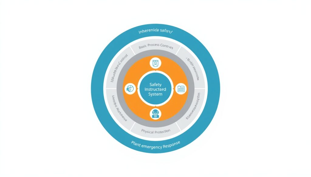
Safety is typically designed in layers, so that if one layer fails, others remain. This concept is called layers of protection.
| Layer | Description | Examples |
|---|---|---|
| 1. Inherent safety | Design features that eliminate or reduce hazards | Using less hazardous materials, reducing inventory |
| 2. Basic process control | Control systems that keep the process within safe limits | Control loops, process alarms |
| 3. Critical alarms and operator response | Alarms that prompt operator action before a trip | High-priority alarms with defined response procedures |
| 4. Safety instrumented systems | Independent systems that bring the plant to a safe state | Emergency shutdown systems |
| 5. Physical protection | Devices that contain or relieve pressure | Relief valves, rupture discs, dikes |
| 6. Plant emergency response | Procedures and equipment for responding to incidents | Fire fighting, evacuation |
| 7. Community emergency response | External response for major incidents | Fire department, emergency services |
The layers work together. No single layer is perfect, but together they provide defense in depth.
Independence matters. In a formal analysis such as LOPA, a layer is credited as an independent protection layer (IPL) only if it is independent of the initiating event and the other layers, specific to the hazard, dependable, and auditable. For example, if the same control loop both causes a deviation and is relied on to prevent it, the two layers are not independent. Community emergency response is generally not credited as an IPL, because it does not prevent the incident.
Hazard Identification
Safety system design begins with hazard identification. You cannot protect against hazards you have not identified.
| Method | Description | Best For |
|---|---|---|
| HAZOP | Systematic review of process deviations using guide words | Process systems |
| HAZID | Structured early-stage identification of hazards | Concept and layout stages |
| What-if analysis | Brainstorming “what if” scenarios | Any system |
| Checklist | Review against a list of known hazards | Routine operations |
| FMEA | Identifying failure modes and their effects | Equipment and systems |
For small plants, a combination of HAZOP for process systems and checklists for routine operations is often practical. HAZID is useful at the concept stage, and FMEA is used for higher-consequence equipment and systems.
Process hazard analyses (PHAs) are not one-time exercises. They should be revalidated periodically (commonly every five years, or as required by local regulation) and whenever significant changes occur.
Hazardous area classification. Where flammable gases, vapors, or dusts may be present, the plant must be classified into hazardous zones (for example, under IEC 60079 or NFPA 70/NEC). Classification determines the electrical equipment and ignition-source controls required, and it should be completed early, because it affects layout and equipment selection.
Risk Assessment
Hazard identification is followed by risk assessment. Risk is the combination of:
- Likelihood: How likely is the hazard to cause harm?
- Consequence: How severe would the harm be?
Risk assessment approaches:
- Qualitative: Using descriptive categories (high, medium, low).
- Semi-quantitative: Using numerical scales for likelihood and consequence, such as a risk matrix or LOPA.
- Quantitative: Using numerical probabilities and consequences (QRA).
For most plant applications, a risk matrix or LOPA is sufficient. The result is compared with the owner’s tolerable risk criteria and determines how much protection is needed. Many organizations apply the ALARP principle (as low as reasonably practicable) to risks in the intermediate range.
Layer of Protection Analysis (LOPA) is commonly used to determine the SIL required for a SIF. It compares the frequency of the initiating event and the protection layers already in place against the tolerable risk, and the remaining gap defines the risk reduction the SIF must provide.
Safety Instrumented Systems (SIS)
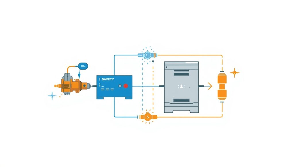
A Safety Instrumented System (SIS) is an independent system designed to bring the plant to a safe state when abnormal conditions occur. It is separate from the basic process control system (BPCS).
A SIS consists of three parts:
- Sensors: Measure process conditions (pressure, temperature, level, flow).
- Logic solver: Evaluates the sensor signals and decides when to act.
- Final elements: Carry out the safety action (shutdown valves, motor trips).
Key concepts:
- Safety Instrumented Function (SIF): A specific safety function, such as closing a valve or tripping a pump.
- Safety Integrity Level (SIL): A measure of the reliability required for a SIF. SIL 1 is the lowest and SIL 4 the highest.
- Proof testing: Periodic testing to verify that the SIS functions correctly and to reveal dangerous failures not detected by diagnostics.
- Independence: The SIS must be separate from the BPCS. Any sharing of components must be justified and its effect on integrity assessed.
SIL levels (low-demand mode):
| SIL | Average Probability of Failure on Demand (PFDavg) | Risk Reduction Factor | Notes |
|---|---|---|---|
| SIL 1 | 10⁻¹ to 10⁻² | 10 to 100 | Lowest required reliability |
| SIL 2 | 10⁻² to 10⁻³ | 100 to 1,000 | Common in process plants |
| SIL 3 | 10⁻³ to 10⁻⁴ | 1,000 to 10,000 | For the highest-consequence hazards |
| SIL 4 | 10⁻⁴ to 10⁻⁵ | 10,000 to 100,000 | Outside the scope of IEC 61511; rarely applicable in process plants |
The SIL of a SIF is set by the risk reduction it must deliver, not by the general “riskiness” of the plant. For small to medium-scale plants, most SIFs are SIL 1 or SIL 2, and SIL 3 is used for the highest-consequence hazards. If a SIF would need SIL 3 or higher, consider whether the process can be made inherently safer first.
Architecture and diagnostics. The achieved SIL depends on the failure rates of the components, the voting architecture (such as 1oo1, 1oo2, or 2oo3), diagnostic coverage, and the proof test interval. Redundant architectures can improve safety, and voting schemes such as 2oo3 can also reduce spurious trips, which are themselves a hazard because shutdowns and restarts stress the plant.
Bypasses and overrides. Bypasses are sometimes necessary for maintenance or startup, but they remove protection. They should be authorized, time-limited, alarmed, and tracked, with compensating measures in place while they are active.
Functional Safety Management
SIS reliability depends not just on design but on management over the lifecycle. Functional safety management covers the entire SIS lifecycle, from hazard identification through design, installation, operation, and maintenance. It includes procedures for change management, proof testing, and competency of personnel.
In practice, this means a defined functional safety plan, assigned responsibilities, periodic functional safety audits and assessments, and records that show each SIF continues to perform as required.
Fire and Gas Detection
Fire and gas detection systems detect fires, flammable gas releases, and toxic gas releases.
Fire detection:
- Smoke detectors: Detect smoke from combustion.
- Heat detectors: Detect temperature rise.
- Flame detectors: Detect ultraviolet or infrared radiation from flames.
- Manual call points: Allow people to raise the alarm.
Gas detection:
- Flammable gas detectors: Detect combustible gas or vapor, typically alarming at a fraction of the lower flammable limit.
- Toxic gas detectors: Detect toxic gases at concentrations relevant to exposure limits.
Key considerations:
- Coverage: Detectors must cover all areas where hazards may occur. Placement should reflect the gas density, ventilation, and likely leak sources.
- Redundancy and voting: Critical areas may require redundant detectors and voting logic to balance reliability against spurious activation.
- Alarm logic: Detection should trigger alarms and, where appropriate, automatic protective actions, such as shutdown, isolation, ventilation change, or suppression release.
- Testing: Detectors must be tested and calibrated periodically.
Fire Protection Systems
Fire protection includes both passive and active systems.
Passive fire protection:
- Fire-resistant construction: Materials and assemblies that resist fire spread.
- Fire walls and barriers: Physical barriers that contain fire.
- Fire doors: Doors that resist fire spread.
- Cable protection: Fire-resistant coatings or enclosures.
- Structural fireproofing: Protection of supports for vessels and pipe racks.
- Containment and drainage: Dikes and drainage that limit the spread of burning liquids.
Active fire protection:
- Sprinkler and water spray systems: Automatic water-based suppression and cooling.
- Foam systems: For flammable liquid fires.
- Gas suppression systems: For electrical or control rooms (for example, inert gases or clean agents). CO₂ can be lethal in occupied spaces, so it requires pre-discharge alarms, time delays, lockouts, and strict life-safety controls.
- Fire hydrants and monitors: For manual fire fighting.
- Fire pumps and water supply: Ensure adequate water quantity and pressure for the design fire scenario.
For small plants, the fire protection strategy should be based on the fire hazards present, the value of the assets, and local regulations and codes (such as NFPA standards where applicable). Passive protection is especially valuable because it works without power, detection, or human action.
Siting and layout. Spacing between units, separation of ignition sources, location of control rooms and occupied buildings, and access for emergency vehicles all reduce the consequences of an incident before any active system is needed. Layout decisions made early are the cheapest safety measures.
Emergency Shutdown Systems
Emergency shutdown (ESD) systems bring the plant to a safe state quickly when a serious abnormal condition occurs.
Key considerations:
- Shutdown philosophy: What conditions trigger a shutdown? What is the safe state?
- Shutdown levels: Different levels for different severities (for example, unit shutdown vs. plant shutdown).
- Valve closure times: How quickly must valves close, and do they fail to the safe position?
- Depressurization: Where is depressurization or blowdown required?
- Manual initiation: Push buttons in safe, accessible locations.
- Restart procedures: How is the plant restarted safely after a shutdown?
ESD systems are typically part of the SIS and must meet the required SIL. They are normally linked to the fire and gas system, but the interface must be clearly defined so that a detection event triggers the intended level of shutdown.
Pressure Relief Systems
Pressure relief systems protect equipment from overpressure. They are the last line of defense against overpressure.
Relief device types:
- Spring-loaded pressure relief valves: Open when pressure exceeds the set point and reclose when it falls.
- Rupture discs: Burst at a set pressure and do not reclose.
- Pilot-operated relief valves: Use a pilot valve to control the main valve.
Key considerations:
- Scenario identification: Determine credible overpressure causes, such as blocked outlet, fire exposure, thermal expansion, control valve failure, and tube rupture.
- Sizing: Relief devices must be sized for the governing (maximum) relief case, following recognized standards such as API 520/521 and ASME Section VIII.
- Set pressure: Set at or below the equipment’s maximum allowable working pressure (MAWP), with allowance for accumulation.
- Discharge location: Relief discharge must be routed to a safe location, such as a flare, scrubber, or safe vent, with attention to backpressure and reaction forces.
- Isolation valves: Block valves upstream or downstream of relief devices must be locked or car-sealed open, or otherwise controlled.
- Testing: Relief devices must be inspected, tested, and maintained periodically.
- Documentation: Sizing, testing, and maintenance must be documented.
Safety Instrumented System Design
Designing a SIS requires several steps.
| Step | Description |
|---|---|
| 1. Identify SIFs | Which safety functions are required? |
| 2. Determine SIL | What SIL is required for each SIF? |
| 3. Prepare the safety requirements specification (SRS) | What must each SIF do, how fast, and what is the safe state? |
| 4. Design the SIS | What sensors, logic solvers, and final elements are needed? |
| 5. Verify SIL | Does the design meet the required SIL, considering architecture, failure rates, and test intervals? |
| 6. Implement | Install, configure, and test the SIS. |
| 7. Validate | Confirm that the SIS functions as specified in the SRS. |
| 8. Operate and maintain | Proof test, manage bypasses, and maintain the SIS over its life. |
SIS design must follow applicable standards, such as IEC 61511 (process industry) or IEC 61508 (general functional safety). Equivalent national adoptions, such as ANSI/ISA-61511 (formerly ISA-84), are also widely used.
Alarm Management
Alarms are a key layer of protection, but poorly managed alarms can overwhelm operators. Alarm management ensures that alarms are meaningful and actionable. Too many alarms, or alarms that operators routinely ignore, undermine the protection they are meant to provide.
Good alarm management practice includes:
- Rationalization: Each alarm has a purpose, a defined operator response, and a priority.
- Prioritization: Critical alarms stand out from advisory ones.
- Limiting alarm floods: Alarms during upsets should be manageable and not overwhelm the operator.
- Change control: Alarm limits and priorities are not changed without review.
- Performance monitoring: Alarm rates and frequently occurring “bad actors” are tracked and corrected.
Recognized guidance includes ISA-18.2 and IEC 62682. Alarms should not be used as a substitute for a SIF where independent, automatic protection is required.
Management of Change (MOC)
Changes to equipment, procedures, or operating conditions can invalidate safety analyses. Management of change (MOC) ensures that changes are reviewed for safety impact before implementation. A change that seems minor can affect the validity of a HAZOP, an SIS design, or a relief system sizing.
An effective MOC process includes:
- Defining what counts as a change (temporary and permanent, including software and set point changes).
- Reviewing safety, health, and environmental impact before approval.
- Updating documentation such as P&IDs, procedures, cause-and-effect charts, and relief calculations.
- Training affected personnel before the change is implemented.
- Closing out temporary changes so they do not become permanent by default.
Human Factors
Human factors engineering considers how people interact with systems. It covers control room design, alarm presentation, procedure clarity, and workload. Good human factors design reduces the likelihood of operator error.
Practical examples include clear and consistent control displays, logical equipment labeling, procedures that can be followed under stress, sensible shift and staffing arrangements, and operator input during design reviews. Even a well-engineered safety system can fail if operators cannot understand or use it when it matters.
Emergency Response Planning
Even well-designed plants must be prepared for incidents. Emergency response planning connects the plant’s safety systems with people and procedures.
Key elements:
- Emergency plan: Defined roles, communication, and decision authority.
- Scenarios: Plans based on credible incidents identified in the hazard analysis (fire, toxic release, explosion, spill).
- Alarms and communication: Ways to alert everyone on site and contact external services.
- Evacuation and muster: Clear routes, assembly points, and headcount procedures.
- Equipment and resources: Fire fighting equipment, first aid, spill response, and personal protective equipment.
- Training and drills: Regular exercises, including coordination with local emergency services.
- Review: Lessons from drills and incidents are captured and applied.
Safety Culture
Safety systems are only effective if they are supported by a strong safety culture.
Key elements of safety culture:
- Leadership commitment: Safety starts at the top.
- Employee involvement: Workers at all levels participate in safety.
- Open reporting: Incidents and near-misses are reported without fear.
- Learning organization: Lessons are captured and applied.
- Continuous improvement: Safety performance is measured and improved.
Safety culture is not a document. It is the way people behave when no one is watching.
Common Mistakes in Safety System Design
Even experienced designers make mistakes. Common ones include:
- Incomplete hazard identification: Missing hazards that later cause incidents.
- Underestimating risk: Assuming hazards are less likely or less severe than they are.
- Inadequate independence: SIS not truly independent of the basic control system, or protection layers that share a common cause of failure.
- Poor proof testing: Safety systems that are not tested, or tested incorrectly.
- Ignoring human factors: Designing systems that operators cannot use effectively.
- Poor alarm management: Alarm floods and nuisance alarms that operators learn to ignore.
- Weak management of change: Modifications that quietly invalidate earlier safety analyses.
- Uncontrolled bypasses: Protection disabled and never restored.
- Weak safety culture: Systems in place, but not respected or followed.
- Insufficient documentation: Making it difficult to maintain and verify safety systems.
These mistakes can have catastrophic consequences. They must be avoided through careful design, testing, and management.
How Japanese EPC Firms Approach Safety Systems
Japanese engineering firms are known for their disciplined approach to safety. Common characteristics include:
- Thorough hazard identification: Hazards are identified systematically, with input from all disciplines.
- Conservative design margins: Safety systems are designed with adequate margin for uncertainty.
- Detailed documentation: Safety analyses, designs, and test records are carefully maintained.
- Comprehensive testing: Safety systems are tested thoroughly before startup and periodically thereafter.
- Disciplined change control: Changes are reviewed and documented before implementation.
- Strong safety culture: Safety is embedded in every aspect of design, construction, and operation.
- Long-term focus: Safety systems are maintained and improved over the plant’s life.
For plant owners, this often means fewer incidents, better regulatory compliance, and a safer workplace.
How to Evaluate Safety System Design
When reviewing safety system design, ask:
| Question | Why It Matters |
|---|---|
| Have all hazards been identified? | You cannot protect against unknown hazards |
| Has risk been assessed consistently against defined criteria? | Determines how much protection is needed |
| Are protection layers independent? | Ensures defense in depth |
| Is the SIS designed and verified to the required SIL? | Ensures safety functions are reliable enough |
| Is there a functional safety management plan? | Ensures reliability is maintained over the lifecycle |
| Are fire and gas detection systems adequate? | Detects incidents early |
| Are relief systems properly sized and routed? | Prevents overpressure failure |
| Are alarms rationalized and manageable? | Keeps operators effective during upsets |
| Is there an MOC process, and is it followed? | Keeps analyses valid after changes |
| Is proof testing planned and performed? | Verifies that safety systems work |
| Are bypasses controlled? | Prevents protection from being lost unnoticed |
| Are emergency response plans tested? | Ensures people can act when needed |
| Is safety culture strong? | Ensures systems are respected and followed |
A plant that addresses these questions is likely to have effective safety systems.
Key Takeaways
- Safety systems protect people, the environment, and the plant
- Layers of protection provide defense in depth, but only if the layers are truly independent
- Hazard identification is the foundation of safety design
- Safety instrumented systems must be independent and designed to the required SIL
- Functional safety management, alarm management, and management of change keep safety systems effective over the plant’s life
- Human factors design reduces the likelihood of operator error
- Fire protection includes both passive and active systems
- Pressure relief systems are the last line of defense against overpressure
- Safety culture determines whether systems are respected and followed
- Japanese EPC firms emphasize thorough hazard identification and comprehensive testing
Conclusion
Safety systems are essential to protecting people, the environment, and the plant itself. For small to medium-scale industrial plants, safety system design deserves careful attention from the earliest stages of design.
By focusing on hazard identification, risk assessment, layers of protection, SIS design and functional safety management, fire protection, alarm management, management of change, and safety culture, owners and designers can ensure that the plant operates safely throughout its life.