Category: Plant Design & Engineering

Technical insights on industrial plant layout, system design, equipment selection, and engineering considerations for thermal, biomass, and process plants.

  • Corrosion Control in Industrial Plants: Materials, Coatings, and Cathodic Protection

    Corrosion Control in Industrial Plants: Materials, Coatings, and Cathodic Protection

    Corrosion is one of the most persistent and costly problems in industrial plants. It attacks pipes, tanks, structures, and equipment, reducing their strength, causing leaks, and eventually leading to failure. According to industry studies, corrosion costs industrial plants billions of dollars annually in maintenance, repair, and lost production.

    For small to medium-scale industrial plants, corrosion control is especially critical because there is less redundancy and fewer resources to manage unexpected failures. A corroded pipe that leaks or bursts can shut down the plant, create safety hazards, and require costly repairs.

    This article covers the fundamentals of corrosion control in industrial plants, including the mechanisms of corrosion, material selection, coatings, cathodic protection, and monitoring.

    What Is Corrosion?

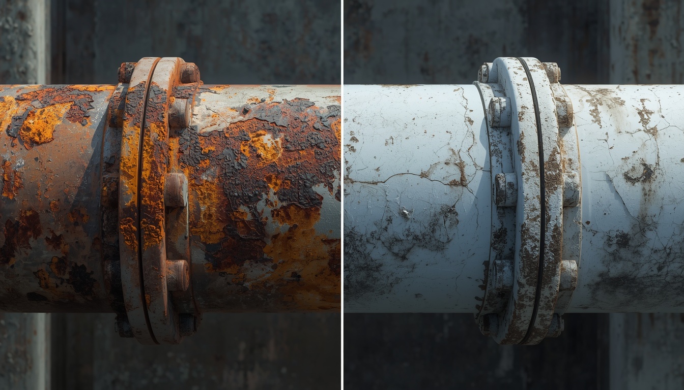
    Corrosion is the deterioration of a material—usually a metal—due to chemical or electrochemical reaction with its environment. For iron and steel, corrosion typically takes the form of rust, which is iron oxide.

    Corrosion occurs when three conditions are present:

    • An anode: The site where metal dissolves.
    • A cathode: The site where reduction occurs.
    • An electrolyte: A conductive medium (water, soil, or humid air) that connects the anode and cathode.

    If any of these three is eliminated, corrosion stops. Corrosion control strategies work by interrupting one or more of these conditions.

    Common Types of Corrosion
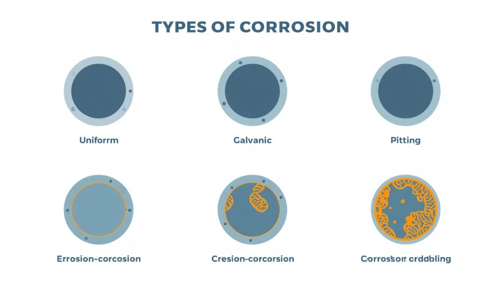
    Types of corrosion in industrial plants

    Corrosion takes many forms. Understanding the type helps in selecting the right control method.

    Type Description Typical Locations
    Uniform corrosion Even attack over the entire surface Carbon steel in general service
    Galvanic corrosion Attack at the junction of dissimilar metals Flanges, fittings, transitions
    Pitting corrosion Localized attack creating deep pits Stainless steels in chloride environments
    Crevice corrosion Attack in stagnant crevices Gaskets, bolt holes, under deposits
    Erosion-corrosion Accelerated attack due to flow Pumps, bends, tees
    Stress corrosion cracking Cracking under combined stress and corrosive environment High-temperature, chloride environments
    Microbiologically influenced corrosion (MIC) Corrosion caused by microorganisms Cooling water, stagnant areas

    Different types of corrosion require different control strategies. A single approach is rarely sufficient.

    One form worth calling out on its own is corrosion under insulation (CUI). It is a particularly insidious form of corrosion because it is hidden from view. Insulation can trap moisture against the metal surface, causing corrosion that goes undetected until failure. Proper insulation design, including vapor barriers and drainage, is essential. (This topic is covered in more detail in the piping systems article.)

    Material Selection

    The first line of defense against corrosion is selecting the right material.

    Common materials and their corrosion resistance:

    Material Corrosion Resistance Typical Use
    Carbon steel Low to moderate General service with protective measures
    Stainless steel High (with limitations) Corrosive fluids, food and pharmaceutical
    Duplex stainless steel Very high Chloride environments, seawater
    Nickel alloys Excellent Highly corrosive environments
    Titanium Excellent Seawater, oxidizing chemicals
    Copper alloys Moderate to high Heat exchangers, potable water
    Plastics (PVC, CPVC, HDPE) High Chemicals, water
    FRP (fiberglass reinforced plastic) High Corrosive chemicals

    Material selection depends on:

    • Fluid composition: What chemicals are present, and at what concentration?
    • Temperature: Higher temperatures usually accelerate corrosion.
    • Pressure: Higher pressures require stronger materials.
    • Environment: External corrosion from salt air, chemicals, or soil.
    • Cost: Material cost and life-cycle cost both matter.

    In piping and vessel design, a corrosion allowance is often added to wall thickness to account for expected metal loss over the plant’s life. This is extra wall thickness added to piping and vessels to account for expected metal loss over the design life. The allowance depends on the corrosion rate, the design life, and the required safety margin.

    Protective Coatings

    Coatings provide a barrier between the metal and the corrosive environment. They are one of the most common and cost-effective corrosion control methods.

    Common coating types:

    Coating Type Characteristics Typical Use
    Epoxy Excellent adhesion, chemical resistance Tanks, pipes, structures
    Polyurethane Good weather resistance External surfaces
    Zinc-rich primers Sacrificial protection Steel structures, tanks
    Fusion-bonded epoxy (FBE) Excellent for buried pipelines Buried pipe
    Concrete Mechanical protection, alkaline Buried pipe, marine structures

    Key considerations for coatings:

    • Surface preparation: The surface must be clean, dry, and properly profiled.
    • Application: Coating must be applied at the correct thickness and under the right conditions.
    • Inspection: Coating defects must be detected and repaired.
    • Maintenance: Coatings degrade over time and require repair or replacement.

    Coating failures are often due to poor surface preparation, not the coating itself.

    Cathodic Protection
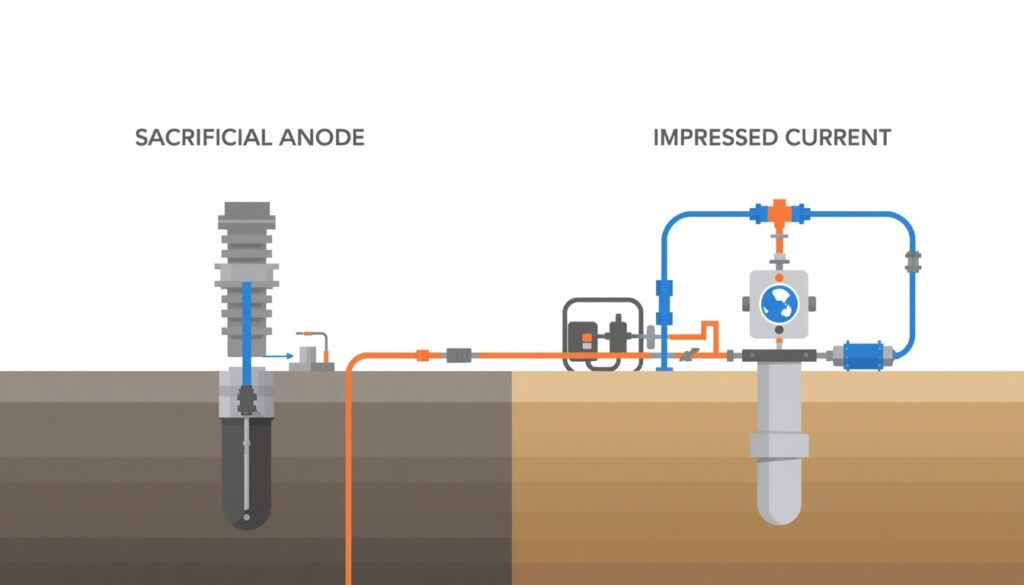
    Sacrificial anode and impressed current cathodic protection systems

    Cathodic protection (CP) is an electrochemical method of corrosion control. It works by making the metal to be protected the cathode of an electrochemical cell, so that it does not corrode.

    There are two main types:

    1. Sacrificial anode systems: A more active metal (such as zinc, aluminum, or magnesium) is connected to the protected structure. The anode corrodes instead of the structure.

    • Simple, no external power required.
    • Suitable for small structures and low-resistivity environments.
    • Anodes must be replaced periodically.

    2. Impressed current systems: An external DC power source supplies current to the structure through an inert anode.

    • Suitable for large structures and high-resistivity environments.
    • Requires external power and regular maintenance.
    • Can be adjusted to meet changing conditions.

    Cathodic protection is commonly used for:

    • Buried pipelines
    • Storage tank bottoms
    • Marine structures
    • Underground tanks

    Corrosion Inhibitors

    Corrosion inhibitors are chemicals that reduce corrosion rates by forming protective films on metal surfaces or by altering the environment. Common types include anodic inhibitors, cathodic inhibitors, and mixed inhibitors. Selection depends on the fluid, material, and operating conditions.

    Corrosion Monitoring

    Monitoring helps detect corrosion before it causes failure.

    Common monitoring methods:

    Method What It Measures Typical Use
    Visual inspection Visible corrosion Accessible surfaces
    Ultrasonic thickness Wall thickness Pipes, tanks, vessels
    Coupons Corrosion rate Process streams
    Electrical resistance probes Corrosion rate Process streams
    Linear polarization resistance (LPR) Corrosion rate Cooling water, process water
    Hydrogen probes Hydrogen permeation High-temperature, sour service

    Monitoring data helps schedule maintenance, adjust treatment programs, and verify that corrosion control measures are working.

    Corrosion Control in Specific Systems

    Different plant systems require different corrosion control strategies.

    Cooling water systems:

    • Chemical inhibitors (corrosion inhibitors, scale inhibitors, biocides)
    • Material selection (stainless steel, copper alloys)
    • Cathodic protection for critical components

    Boiler systems:

    • Water treatment (oxygen removal, pH control)
    • Chemical treatment (oxygen scavengers, pH adjusters)
    • Material selection

    Piping systems:

    • Material selection
    • Coatings (internal and external)
    • Cathodic protection for buried pipes
    • Corrosion monitoring (ultrasonic thickness)
    • Insulation design that avoids trapping moisture, to prevent corrosion under insulation (CUI)

    Storage tanks:

    • Coatings (internal and external)
    • Cathodic protection (tank bottoms)
    • Corrosion monitoring

    Structures:

    • Coatings (external)
    • Cathodic protection (buried or submerged)
    • Material selection

    Key Design Considerations

    1. Corrosion Risk Assessment Identify where corrosion is likely to occur and what type is expected. This determines the control strategy.

    2. Material Selection Select materials compatible with the fluid, temperature, pressure, and environment.

    3. Protective Measures Combine coatings, cathodic protection, and chemical treatment as needed. No single method is sufficient for all situations.

    4. Monitoring Implement monitoring to detect corrosion before it causes failure.

    5. Maintenance Inspect, repair, and replace coatings and anodes as needed.

    6. Documentation Record material selection, coating specifications, cathodic protection design, and monitoring data.

    Corrosion Management Programs

    Corrosion control is not just a design issue. It requires an ongoing program. An effective corrosion management program includes regular inspection, monitoring, maintenance, and documentation. It assigns responsibility for corrosion control and ensures that issues are identified and addressed before they cause failure.

    Common Mistakes in Corrosion Control

    Even experienced designers make mistakes. Common ones include:

    • Selecting the wrong material: Incompatible with the fluid or environment.
    • Poor surface preparation: Causing coating failure.
    • Inadequate cathodic protection design: Failing to protect the entire structure.
    • Ignoring monitoring: Discovering corrosion only after failure.
    • Skipping maintenance: Letting coatings and anodes degrade.
    • Incomplete documentation: Making it difficult to troubleshoot and maintain.

    These mistakes are costly to fix after construction. They are much cheaper to avoid during design.

    How Japanese EPC Firms Approach Corrosion Control

    Japanese engineering firms are known for their disciplined approach to corrosion control. Common characteristics include:

    • Thorough risk assessment: Corrosion risks are identified early in design.
    • Conservative material selection: Materials are selected with adequate margin for the expected environment.
    • Detailed coating specifications: Surface preparation, application, and inspection are carefully specified.
    • Comprehensive monitoring: Corrosion is monitored throughout the plant’s life.
    • Long-term maintenance focus: Corrosion control is treated as an ongoing responsibility, not a one-time design decision.

    For plant owners, this often means lower maintenance costs and fewer unexpected failures over the plant’s life.

    How to Evaluate Corrosion Control Design

    When reviewing corrosion control design, ask:

    Question Why It Matters
    Has a corrosion risk assessment been performed? Identifies where corrosion is likely
    Are materials compatible with the fluid and environment? Prevents corrosion from the start
    Are coatings properly specified? Ensures effective barrier protection
    Is cathodic protection designed correctly? Ensures complete protection
    Is monitoring in place? Detects corrosion before failure
    Is maintenance planned? Ensures long-term effectiveness
    Is documentation complete? Supports troubleshooting and maintenance

    A design that addresses these questions is likely to perform well over the plant’s life.

    Key Takeaways

    • Corrosion requires an anode, a cathode, and an electrolyte
    • Common types include uniform, galvanic, pitting, crevice, erosion-corrosion, and MIC
    • Material selection is the first line of defense
    • Coatings provide a barrier between metal and environment
    • Cathodic protection uses sacrificial anodes or impressed current
    • Monitoring detects corrosion before failure
    • Japanese EPC firms emphasize thorough risk assessment and conservative material selection

    Conclusion

    Corrosion is a persistent and costly problem in industrial plants, but it can be controlled. By combining material selection, coatings, cathodic protection, and monitoring, owners and designers can protect equipment and structures from corrosion and extend their service life.

    For small to medium-scale industrial plants, where margins are tight, corrosion control deserves careful attention from the earliest stages of design.
  • Piping Systems for Industrial Plants: Key Design Considerations

    Piping Systems for Industrial Plants: Key Design Considerations

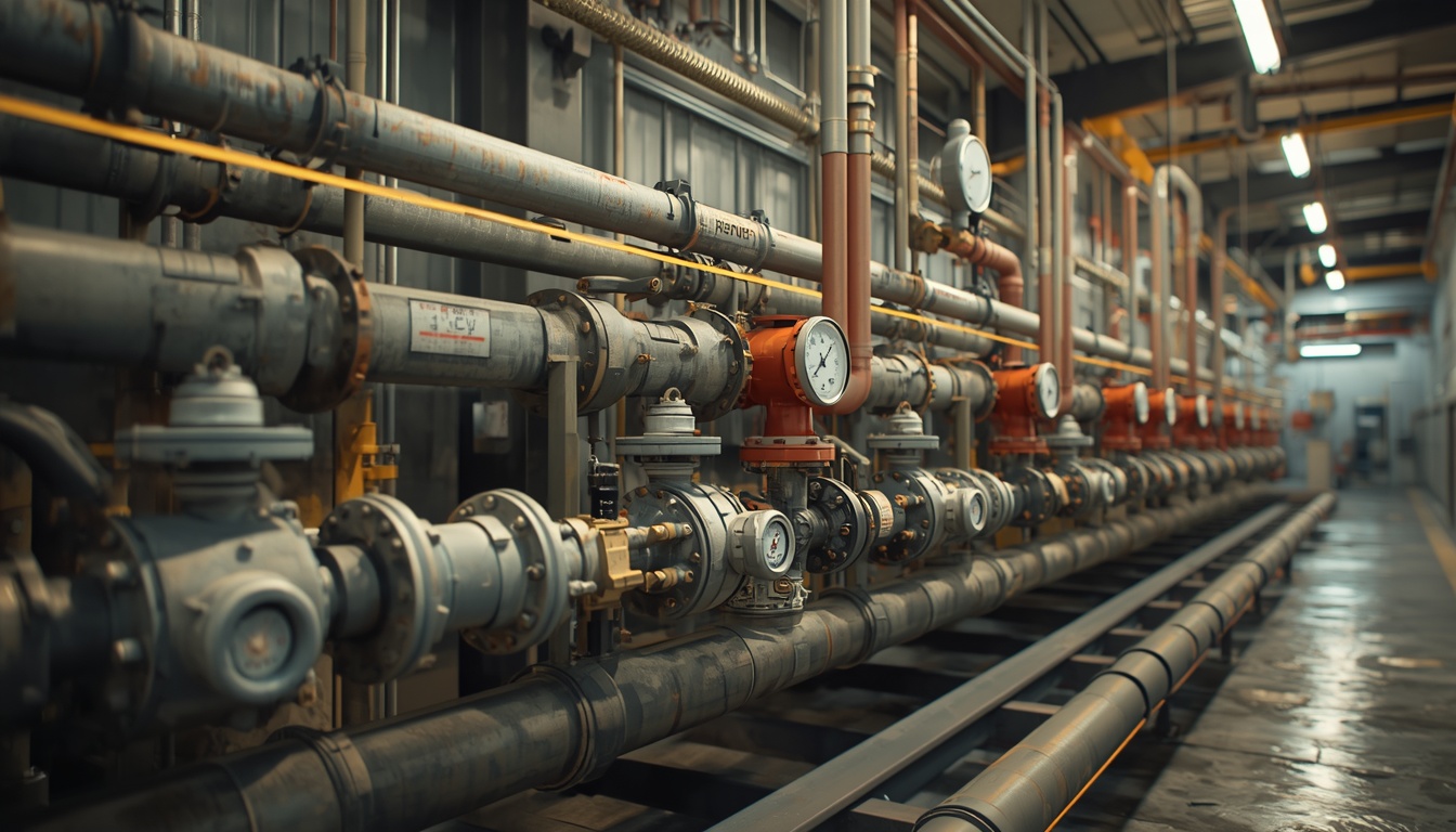
    Piping systems are the circulatory system of an industrial plant. They transport fluids—water, steam, fuel, chemicals, and gases—between equipment and processes. A well-designed piping system ensures reliable flow, minimizes pressure loss, and operates safely for decades. A poorly designed system causes pressure drops, vibration, corrosion, and leaks that disrupt operations and create safety hazards.

    For small to medium-scale industrial plants, piping design is especially critical because there is less redundancy and fewer resources to manage complexity. Piping often represents a significant portion of total plant cost, and mistakes are expensive to correct after construction.

    This article covers the key considerations in piping system design for industrial plants, from material selection to layout, support, and testing.

    The Role of Piping Systems

    Piping systems perform several essential functions:

    • Transport: Moving fluids from one point to another.
    • Containment: Keeping fluids safely contained under pressure and temperature.
    • Isolation: Allowing sections of the system to be isolated for maintenance or emergencies.
    • Control: Working with valves and instruments to regulate flow, pressure, and temperature.
    • Protection: Safely relieving excess pressure through relief valves and venting.

    Piping is not just a collection of pipes. It is a system that includes pipe, fittings, valves, flanges, gaskets, supports, insulation, and instruments. All components must work together to ensure safe, reliable operation.

    Piping Materials

    Material selection is one of the most important decisions in piping design. The material must be compatible with the fluid, temperature, pressure, and environment.

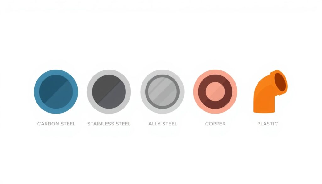
    Common piping materials include:

    Material Typical Use Key Characteristics
    Carbon steel Steam, water, oil, gas Strong, economical, but corrodes
    Stainless steel Corrosive fluids, high temperature Corrosion-resistant, expensive
    Alloy steel High-temperature, high-pressure service Retains strength at high temperature
    Copper Instrument air, potable water Corrosion-resistant, but limited temperature range
    Plastic (PVC, CPVC, HDPE) Water, chemicals Corrosion-resistant, limited temperature and pressure
    Fiberglass reinforced plastic (FRP) Corrosive chemicals Corrosion-resistant, lightweight

    Material selection depends on:

    • Fluid composition: Corrosive, abrasive, or reactive fluids require special materials.
    • Temperature: High temperature reduces material strength and increases corrosion rates.
    • Pressure: High pressure requires thicker walls and stronger materials.
    • Environment: External corrosion from salt air, chemicals, or soil must be considered.
    • Cost: Material cost and life-cycle cost both matter.

    Pipe Sizing

    Pipe size affects pressure drop, flow velocity, and cost. Pipes that are too small cause excessive pressure drop; pipes that are too large waste material and space.

    Key sizing considerations:

    • Flow rate: The required flow rate, together with the allowable velocity and pressure drop, determines the pipe size.
    • Velocity: Velocity must be high enough to prevent settling but low enough to avoid erosion and noise.
    • Pressure drop: Pressure drop must be within acceptable limits for the system.
    • Future capacity: Consider whether future flow increases are likely.

    Typical velocity guidelines:

    Fluid Recommended Velocity
    Water (pump discharge) 2–4 m/s
    Water (suction) 0.5–1.5 m/s
    Steam (saturated) 20–40 m/s
    Compressed air 10–20 m/s
    Viscous fluids 0.5–2 m/s

    These are general guidelines. Specific limits depend on the fluid, material, and application.

    Piping Layout

    Layout determines how piping is routed through the plant. Good layout minimizes length, avoids conflicts, and allows access for maintenance.

    Key layout considerations:

    • Route directly: Shorter routes reduce pressure drop and material cost.
    • Avoid unnecessary bends: Every bend adds pressure drop and cost.
    • Allow for expansion: Piping expands and contracts with temperature changes. Loops, offsets, and expansion joints accommodate this movement.
    • Provide access: Valves, instruments, and flanges must be accessible for operation and maintenance.
    • Avoid interference: Piping must not interfere with equipment access, walkways, or other systems.
    • Slope for drainage: Piping that carries liquids should slope to drain points.
    • Consider pipe racks: Grouping pipes in racks saves space and simplifies support.

    Expansion joints. Expansion joints (bellows, slip, or articulated) accommodate thermal movement where loops are not practical. However, they require careful design and maintenance because they are a common source of leaks. They must also be properly anchored and guided so that pressure thrust does not overload the joint or the connected equipment.

    Pipe Supports

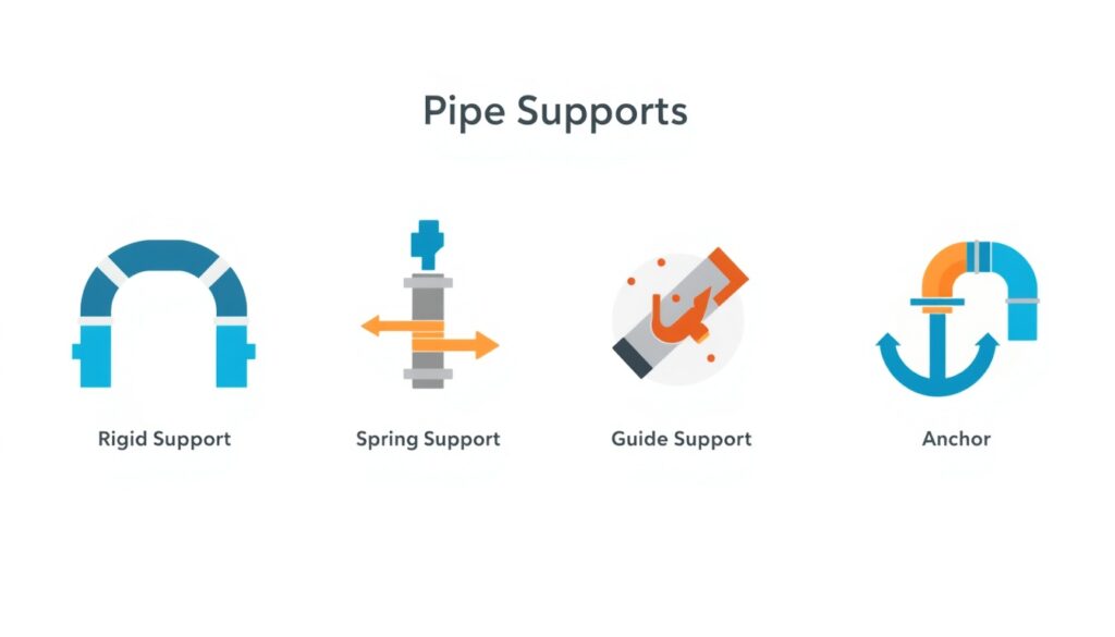
    Types of pipe supports for industrial piping systems

    Pipe supports carry the weight of piping and control movement due to thermal expansion, vibration, and other forces.

    Types of supports:

    • Rigid supports: Carry the weight of the pipe and restrict vertical movement, typically allowing horizontal sliding.
    • Spring supports: Allow vertical movement while supporting weight.
    • Guide supports: Allow axial movement while preventing lateral movement.
    • Anchors: Prevent all movement at a specific point.
    • Snubbers: Allow slow movement but resist rapid movement (e.g., during earthquakes).

    Support spacing depends on pipe size, material, and contents. Supports must be designed to handle the weight of the pipe, insulation, contents, and any valves or fittings.

    Valves and Fittings

    Valves control flow and allow isolation. Fittings connect pipes and change direction.

    Common valve types:

    Valve Type Function Typical Use
    Gate valve On/off isolation Fully open or closed service
    Globe valve Throttling Flow regulation
    Ball valve On/off isolation Quick operation
    Butterfly valve On/off or throttling Large diameter, low pressure
    Check valve Prevent backflow Pump discharge, critical lines
    Control valve Modulate flow Process control
    Relief valve Protect against overpressure Pressure vessels, piping systems

    Common fitting types:

    • Elbows: Change direction.
    • Tees: Branch flow.
    • Reducers: Change pipe size.
    • Flanges: Connect pipes and equipment for disassembly.

    Insulation and Heat Tracing

    Insulation reduces heat loss or gain and protects personnel from hot or cold surfaces.

    Insulation considerations:

    • Thermal performance: Insulation thickness depends on temperature and desired performance.
    • Personnel protection: Surfaces above 60°C or below 0°C typically require insulation or guarding.
    • Corrosion under insulation (CUI): Insulation can trap moisture and cause corrosion. Proper design and maintenance are essential.
    • Heat tracing: Electric or steam tracing maintains temperature in pipes that would otherwise cool below required levels.

    Pipe Identification and Labeling

    In complex plants, pipes must be identifiable for operation and maintenance. Pipes should be labeled with their contents and flow direction. Color coding and labeling systems help operators and maintenance staff identify lines quickly.

    Pressure Relief and Safety

    Piping systems must be protected against overpressure. Relief valves, rupture discs, and venting systems prevent catastrophic failure.

    Key considerations:

    • Relief valve sizing: Must be sized to handle the maximum relief case.
    • Discharge location: Relief discharge must be routed to a safe location.
    • Testing: Relief valves must be tested periodically.
    • Documentation: Relief valve sizing, testing, and maintenance must be documented.

    Water Hammer

    Water hammer occurs when fluid flow is suddenly stopped or changed, causing pressure surges that can damage piping and supports. Common causes include fast-closing valves and pump trips. Proper design includes slow-closing valves, air chambers, and surge suppressors.

    Testing and Commissioning

    Piping systems must be tested before operation to verify integrity and safety.

    Common tests:

    • Hydrostatic test: Fills the system with water and pressurizes to test strength and leak tightness.
    • Pneumatic test: Uses air or inert gas instead of water (used when water is not suitable). Because compressed gas stores much more energy than water, pneumatic tests require additional safety precautions.
    • Flushing: Removes debris and contaminants from the system.
    • Cleaning: Removes scale, rust, and other deposits.
    • Leak test: Verifies that joints and connections do not leak.

    Testing must be documented and witnessed where required.

    Key Design Considerations

    1. Codes and Standards

    Piping systems must comply with applicable codes and standards, such as ASME B31.1 (power piping), ASME B31.3 (process piping), or local equivalents.

    2. Material Compatibility

    Materials must be compatible with the fluid, temperature, and environment. Incompatible materials cause corrosion, contamination, or failure.

    3. Flexibility and Stress Analysis

    Piping must accommodate thermal expansion and other movements without excessive stress. Stress analysis may be required for critical lines. It is typically performed using specialized software such as CAESAR II or AutoPIPE. These tools model the piping system, apply thermal and mechanical loads, and calculate stresses at critical points.

    4. Support and Restraint

    Supports must carry weight and control movement. Restraints must prevent excessive movement without over-stressing the pipe.

    5. Accessibility

    Valves, instruments, and flanges must be accessible for operation and maintenance. Piping should not block access to equipment.

    6. Future Expansion

    Piping systems should be designed with spare capacity for future additions. This includes spare nozzles, spare pipe racks, and spare valves.

    Common Mistakes in Piping Design

    Even experienced designers make mistakes. Common ones include:

    • Undersizing pipes: Causing excessive pressure drop and poor performance.
    • Ignoring thermal expansion: Leading to stress, deformation, or failure.
    • Inadequate support spacing: Causing sagging, vibration, or failure.
    • Poor access to valves and instruments: Making maintenance difficult.
    • Incompatible materials: Causing corrosion or contamination.
    • Missing relief protection: Creating a safety hazard.
    • Ignoring water hammer: Allowing pressure surges to damage piping and supports.
    • Insufficient documentation: Making maintenance and troubleshooting difficult.

    These mistakes are costly to fix after construction. They are much cheaper to avoid during design.

    How Japanese EPC Firms Approach Piping Design

    Japanese engineering firms are known for their disciplined approach to piping design. Common characteristics include:

    • Thorough stress analysis: Critical lines are analyzed carefully for thermal and mechanical stress.
    • Conservative material selection: Materials are selected with adequate margin for corrosion and temperature.
    • Detailed support design: Supports are designed for all expected loads and movements.
    • Comprehensive documentation: Piping drawings, isometrics, and test records are carefully maintained.
    • Long-term reliability focus: Designs prioritize reliability and maintainability over lowest initial cost.

    For plant owners, this often means a piping system that performs reliably for decades, with fewer leaks and less maintenance.

    How to Evaluate Piping Design

    When reviewing piping design, ask:

    Question Why It Matters
    Are pipes sized for actual flow and pressure drop? Ensures proper performance
    Are materials compatible with the fluid and environment? Prevents corrosion and failure
    Is thermal expansion accommodated? Prevents stress and deformation
    Are supports designed for all loads? Prevents sagging and vibration
    Are valves and instruments accessible? Enables operation and maintenance
    Has water hammer been assessed and controlled? Prevents pressure-surge damage
    Is relief protection provided? Prevents overpressure failure
    Does the design comply with applicable codes? Ensures safety and legal operation

    A design that addresses these questions is likely to perform well over the plant’s life.

    Conclusion

    Piping systems are essential to plant reliability, safety, and efficiency. For small to medium-scale industrial plants, piping design deserves careful attention from the earliest stages of design. By focusing on material selection, sizing, layout, support, stress analysis, surge protection, and testing, owners and designers can ensure reliable flow and safe operation for decades.
    Key Takeaways

    • Piping systems transport, contain, isolate, control, and protect
    • Material selection depends on fluid, temperature, pressure, and environment
    • Pipe sizing balances pressure drop, velocity, and cost
    • Layout should minimize length, avoid bends, and allow for expansion
    • Supports carry weight and control movement
    • Testing verifies integrity before operation
    • Japanese EPC firms emphasize thorough stress analysis and detailed support design
  • Instrumentation and Control Systems for Industrial Plants: Key Considerations

    Instrumentation and Control Systems for Industrial Plants: Key Considerations

    Instrumentation and control systems are the eyes, ears, and hands of an industrial plant. They measure process variables, transmit data to control systems, and adjust equipment to maintain safe and efficient operation. Without reliable instrumentation and control, a plant cannot operate consistently, safely, or efficiently.

    For small to medium-scale industrial plants, instrumentation and control design is especially critical because there is less redundancy and fewer resources to manage complexity. The right design ensures reliable measurement, accurate control, and safe operation.

    This article covers the key considerations in instrumentation and control system design for industrial plants, from sensor selection to control system architecture.

    The Role of Instrumentation and Control

    Instrumentation and control systems perform several essential functions:

    • Measurement: Sensors measure temperature, pressure, flow, level, and other process variables.
    • Transmission: Signals are transmitted from field instruments to control systems.
    • Control: Control systems adjust valves, motors, and other actuators to maintain desired conditions.
    • Monitoring: Operators monitor process conditions through displays and alarms.
    • Safety: Safety instrumented systems (SIS) protect the plant during abnormal conditions.
    • Data logging: Historical data supports troubleshooting, optimization, and compliance.

    Without reliable instrumentation and control, operators cannot know what is happening in the process, and equipment cannot respond to changing conditions.

    Key Instrumentation Types

    Different process variables require different types of instruments.

    Variable Common Instrument Types
    Temperature Thermocouples, RTDs, thermistors
    Pressure Pressure gauges, transmitters, switches
    Flow Orifice plates, vortex meters, Coriolis meters, ultrasonic meters
    Level Float switches, radar, ultrasonic, differential pressure
    Analytical pH, conductivity, oxygen, gas analyzers
    Position Limit switches, encoders, proximity sensors

    Each instrument type has advantages and limitations. Selection depends on accuracy requirements, process conditions, and cost.

    Instrument Selection Considerations

    Choosing the right instrument is critical for reliable measurement.

    1. Accuracy and Range
    Instruments must be accurate enough for the application and cover the expected range of process conditions. Over-specifying accuracy adds cost; under-specifying leads to poor control.

    2. Process Conditions
    Temperature, pressure, corrosion, vibration, and humidity all affect instrument performance. Instruments must be rated for the conditions they will experience.

    3. Response Time
    Some processes require fast-responding instruments; others do not. Response time affects control loop performance.

    4. Installation, Calibration, and Maintenance
    Instruments must be accessible for calibration and maintenance. Installation must comply with manufacturer requirements and applicable standards. Instruments must be calibrated periodically to maintain accuracy. Calibration intervals depend on the instrument type, process conditions, and criticality of the measurement.

    5. Signal Type
    Instruments can transmit analog signals (4–20 mA), hybrid signals such as HART, or fully digital fieldbus communications. The choice affects wiring, control system compatibility, and diagnostic capability. Fieldbus and digital communications protocols (such as HART, Profibus, or Foundation Fieldbus) allow instruments to transmit diagnostic data in addition to process measurements. This enables predictive maintenance and faster troubleshooting.

    6. Certification
    In hazardous areas, instruments must be certified for the applicable area classification (e.g., ATEX, IECEx, or NEC/CEC).

    Control System Types

    The control system receives signals from instruments and sends commands to actuators.

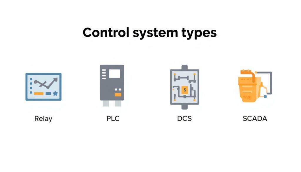
    Type Characteristics Typical Use
    Relay logic Simple, hardwired Small plants, simple processes
    PLC Programmable, flexible, widely supported Most industrial plants
    DCS Distributed, integrated, scalable Large, complex plants
    SCADA Supervisory layer for data acquisition, monitoring, and remote access across PLCs or RTUs Plants requiring remote or centralized monitoring

    For small to medium-scale plants, PLC-based control is common. It offers flexibility, is well-supported by vendors, and can be expanded as the plant grows.

    Control Loop Design

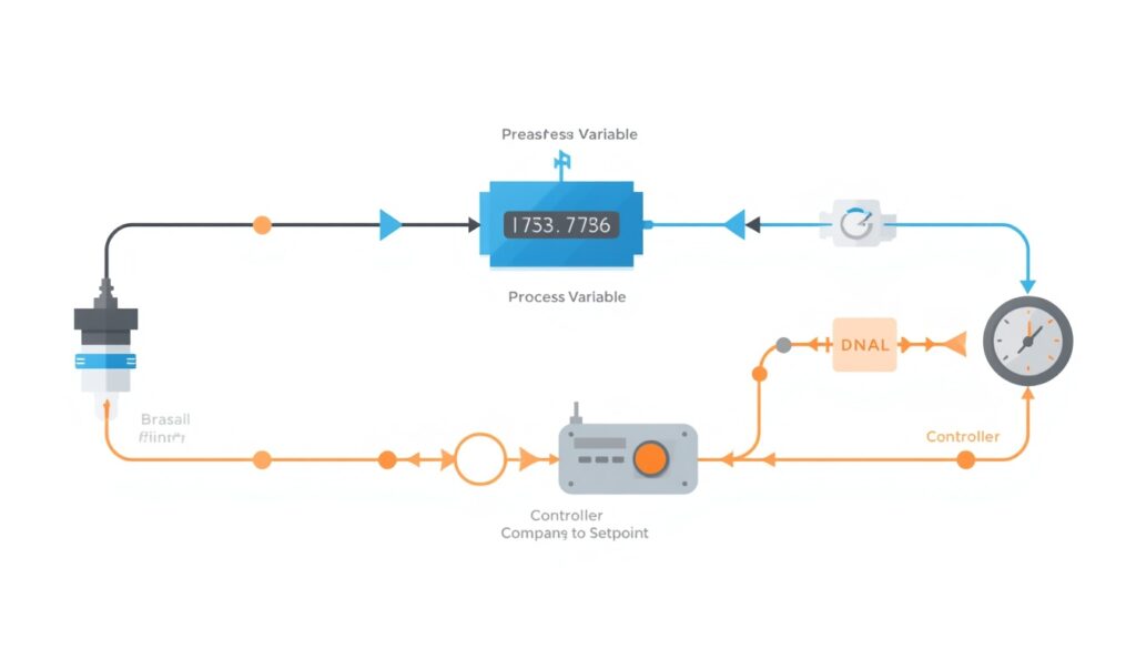
    A control loop consists of a sensor, a controller, and a final control element (such as a valve or motor). The controller compares the measured value to a setpoint and adjusts the final control element to reduce the difference.

    Key control loop considerations:

    • Loop tuning: Controllers must be tuned for stable, responsive control.
    • Loop interaction: Multiple control loops can interact, requiring careful design.
    • Redundancy: Critical loops may require redundant sensors or controllers.
    • Fail-safe positions: Valves and actuators should fail to a safe position on loss of signal or power.

    Safety Instrumented Systems (SIS)

    Safety instrumented systems are independent of the basic process control system and are designed to bring the plant to a safe state during abnormal conditions.

    Key SIS considerations:

    • Safety integrity level (SIL): Determines the required reliability of the SIS.
    • Independence: SIS must be independent of the basic control system.
    • Testing: SIS components must be tested periodically to verify functionality.
    • Documentation: SIS design, testing, and maintenance must be documented.

    Whether a formal SIL-rated SIS is required depends on a hazard and risk assessment, not on plant size alone. For small plants, a full SIS may not be required, but safety interlocks and shutdown systems are still essential.

    Human-Machine Interface (HMI)

    The HMI is how operators interact with the control system. A well-designed HMI improves situational awareness and reduces operator error.

    Key HMI considerations:

    • Clarity: Displays should be clear and uncluttered.
    • Consistency: Similar information should be presented in similar ways.
    • Alarm management: Alarms should be prioritized and actionable.
    • Trending: Historical trends help operators understand process behavior.
    • Accessibility: Displays should be readable from normal operating positions.

    Alarm rationalization is the process of reviewing and prioritizing alarms to ensure they are actionable and meaningful. Too many alarms can overwhelm operators and lead to critical alarms being missed.

    Integration with Other Plant Systems

    Control systems often integrate with other plant systems, including electrical systems, safety systems, and business networks. Integration requires careful planning to avoid conflicts and security risks.

    Cybersecurity for Control Systems

    Control systems are increasingly connected to networks, creating cybersecurity risks. A cyberattack on a control system could disrupt operations or cause safety incidents.

    Key cybersecurity considerations:

    • Network segmentation: Control networks should be separated from business networks.
    • Access control: Only authorized personnel should access control systems.
    • Monitoring: Network traffic and system logs should be monitored for unusual activity.
    • Updates: Control system software and firmware should be kept up to date.
    • Training: Personnel should be trained on cybersecurity awareness.

    Key Design Considerations

    1. Reliability
    Instruments and control systems must be reliable. Critical measurements may require redundant instruments or controllers.

    2. Maintainability
    Instruments must be accessible for calibration, testing, and replacement. Documentation must be clear and complete.

    3. Scalability
    Control systems should be designed with spare capacity for future expansion. This includes spare I/O, spare network capacity, and spare panel space.

    4. Standardization
    Standardizing on common instrument types and control system platforms reduces training, spare parts, and maintenance complexity.

    5. Environmental Conditions
    Instruments and control equipment must be rated for the environmental conditions they will experience, including temperature, humidity, vibration, and corrosion.

    6. Regulatory Compliance
    Instrumentation and control systems must comply with applicable codes and standards, including those for hazardous areas, safety systems, and environmental monitoring.

    Common Mistakes in Instrumentation and Control Design

    Even experienced designers make mistakes. Common ones include:

    • Underspecifying instruments: Leading to poor accuracy or premature failure.
    • Ignoring process conditions: Instruments that cannot handle actual temperature, pressure, or corrosion.
    • Inadequate redundancy: Critical measurements without backup.
    • Poor HMI design: Confusing displays that increase operator error.
    • Neglecting cybersecurity: Control systems exposed to network threats.
    • Insufficient documentation: Making maintenance and troubleshooting difficult.
    • No spare capacity: Requiring costly upgrades for future expansion.

    These mistakes are costly to fix after construction. They are much cheaper to avoid during design.

    How Japanese EPC Firms Approach Instrumentation and Control

    Japanese engineering firms are known for their disciplined approach to instrumentation and control design. Common characteristics include:

    • Thorough specification: Instruments are specified carefully, with attention to accuracy, range, and process conditions.
    • Conservative design margins: Redundancy and spare capacity are provided where justified.
    • Detailed documentation: Loop diagrams, instrument schedules, and test records are carefully maintained.
    • Comprehensive testing: Control loops and safety systems are tested thoroughly before startup.
    • Long-term reliability focus: Designs prioritize reliability and maintainability over lowest initial cost.

    For plant owners, this often means an instrumentation and control system with a long service life and fewer unplanned outages.

    How to Evaluate Instrumentation and Control Design

    When reviewing instrumentation and control design, ask:

    Question Why It Matters
    Are instruments specified for actual process conditions? Ensures reliable measurement
    Is redundancy provided for critical measurements? Ensures continued operation during faults
    Is the control system scalable? Avoids costly upgrades later
    Is the HMI designed for operator effectiveness? Reduces operator error
    Is cybersecurity addressed? Protects against network threats
    Is documentation complete? Supports maintenance and troubleshooting
    Does the design comply with applicable codes? Ensures safety and legal operation

    A design that addresses these questions is likely to perform well over the plant’s life.

    Conclusion

    Instrumentation and control systems are essential to plant reliability, safety, and efficiency. For small to medium-scale industrial plants, instrumentation and control design deserves careful attention from the earliest stages of design. By focusing on instrument selection, control system architecture, safety systems, and cybersecurity, owners and designers can ensure reliable measurement, accurate control, and safe operation for many years.

    Key Takeaways

    • Instrumentation and control systems measure, transmit, control, monitor, and protect
    • Instrument selection depends on accuracy, process conditions, and response time
    • Control system types include relay logic, PLC, DCS, and SCADA
    • Safety instrumented systems (SIS) protect the plant during abnormal conditions
    • HMI design and alarm management affect operator effectiveness
    • Cybersecurity is an increasing concern for control systems
    • Japanese EPC firms emphasize thorough specification and comprehensive testing
  • Electrical Systems for Industrial Plants: Key Design Considerations

    Electrical Systems for Industrial Plants: Key Design Considerations

    Electrical systems are the nervous system of an industrial plant. They power motors, control instruments, provide lighting, and ensure safety systems function when needed. Unlike mechanical systems, which can sometimes be bypassed or operated manually, electrical systems must operate correctly every time. A failure can shut down the entire plant—or worse, create a safety hazard.

    For small to medium-scale industrial plants, electrical system design is especially critical because there is less redundancy and fewer resources to manage complexity. The right design ensures reliable power, safe operation, and room for future expansion.

    This article covers the key considerations in electrical system design for industrial plants, from power supply to distribution, protection, and control.

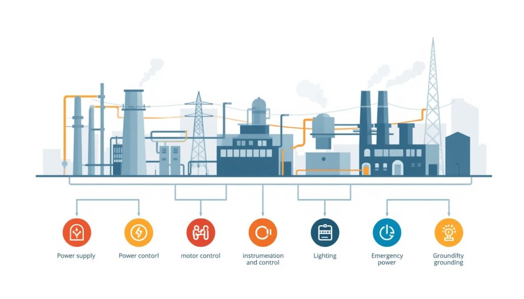
    The Main Electrical Systems in an Industrial Plant

    Main electrical systems in an industrial plant diagram

    An industrial plant’s electrical system can be divided into several subsystems, each with its own function.

    System Purpose
    Power supply Receives power from the grid or on-site generation
    Power distribution Delivers power to equipment throughout the plant
    Motor control Starts, stops, and protects motors
    Instrumentation and control Monitors and controls process variables
    Lighting Provides illumination for operation, maintenance, and safety
    Emergency power Provides backup power for critical systems
    Grounding and lightning protection Protects people and equipment from electrical hazards

    Each subsystem must be designed to work with the others. A weakness in any one can compromise the entire plant.

    Power Supply

    The first decision in electrical system design is how the plant will receive power.

    Grid supply: Most industrial plants receive power from the local utility grid. The supply voltage depends on the utility and the plant’s size. Small plants may receive power at low voltage (e.g., 400 V or 480 V), while larger plants receive power at medium voltage (e.g., 6.6 kV, 11 kV, or 33 kV) and step it down on site.

    On-site generation: Some plants generate their own power using gas turbines, diesel generators, or renewable sources. This provides independence from the grid but adds complexity and cost.

    Combined supply: Many plants use both grid supply and on-site generation. This provides redundancy and allows the plant to operate during grid outages.

    Key considerations for power supply:

    • Reliability: How often does the grid fail, and how long do outages last?
    • Power quality: Voltage sags, harmonics, and frequency variations can affect equipment.
    • Cost: Tariff structures, demand charges, and time-of-use rates affect operating cost.
    • Future expansion: Will the plant need more power later?

    Power Distribution

    Once power enters the plant, it must be distributed to equipment throughout the site.

    Distribution voltages: Plants typically use multiple voltage levels:

    • Medium voltage (e.g., 6.6 kV, 11 kV, 33 kV): For distribution across the site and to large motors.
    • Low voltage (e.g., 400 V, 480 V): For small motors, lighting, and control systems.
    • Extra-low voltage (e.g., 24 V DC): For instrumentation and control.

    Transformers step voltage down between levels.

    Distribution configurations:

    Configuration Characteristics Typical Use
    Radial Simple, single path from source to load Small plants, non-critical loads
    Ring Power feeds from two directions Medium plants, improved reliability
    Network Multiple sources and paths Large plants, high reliability

    For small to medium-scale plants, radial distribution is often sufficient. Ring distribution may be justified for critical loads.

    Key considerations for power distribution:

    • Voltage drop: Long cable runs cause voltage drop, which affects motor performance.
    • Cable sizing: Cables must be sized for current, voltage drop, and short-circuit withstand.
    • Routing: Cables should be routed away from hot surfaces, moisture, and mechanical damage.
    • Segregation: Power and instrument cables should be segregated to avoid interference.

    Power factor correction: Many utilities charge penalties for low power factor. Power factor correction capacitors or synchronous condensers may be required to maintain power factor above a specified threshold.

    Harmonics and filtering: Non-linear loads such as VFDs and rectifiers generate harmonics that can distort voltage and affect sensitive equipment. Harmonic filters or active compensators may be required.

    Motor Control

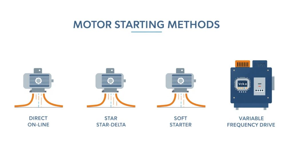
    Comparison of motor starting methods for industrial plants

    Motors are the largest electrical loads in most industrial plants. They drive pumps, fans, compressors, and conveyors.

    Motor starting: Large motors draw high starting current, which can cause voltage dips. Starting methods include:

    • Direct-on-line (DOL): Simple but high starting current.
    • Star-delta: Reduces starting current but adds complexity.
    • Soft starter: Gradually increases voltage to reduce starting current.
    • Variable frequency drive (VFD): Controls motor speed and torque, with low starting current.

    Motor protection: Motors must be protected against:

    • Overload: Excessive current due to mechanical or electrical faults.
    • Short circuit: Faults that cause very high current.
    • Phase loss: Loss of one phase in a three-phase supply.
    • Earth fault: Current leaking to ground.

    Protection devices include overload relays, circuit breakers, and earth fault relays.

    Key considerations for motor control:

    • Starting method: Depends on motor size, load characteristics, and grid strength.
    • Protection coordination: Protection devices must coordinate to isolate faults without unnecessary trips.
    • Control philosophy: Local vs. remote control, manual vs. automatic operation.

    Instrumentation and Control

    Instrumentation and control systems monitor process variables and adjust equipment to maintain desired conditions.

    Control system types:

    Type Characteristics Typical Use
    Relay logic Simple, hardwired Small plants, simple processes
    PLC Programmable, flexible Most industrial plants
    DCS Distributed, integrated Large, complex plants
    SCADA Supervisory control and data acquisition Plants requiring remote monitoring

    For small to medium-scale plants, PLC-based control is common. It offers flexibility and is well-supported by vendors.

    Key considerations for instrumentation and control:

    • Signal types: Analog (4–20 mA), digital, and fieldbus communications.
    • Redundancy: Critical control loops may require redundant sensors or controllers.
    • Cybersecurity: Control systems are increasingly connected to networks, creating security risks.
    • Human-machine interface (HMI): Operators need clear, intuitive displays.

    Lighting

    Lighting is often overlooked but essential for safe operation and maintenance.

    Lighting types:

    • General lighting: Illuminates work areas.
    • Task lighting: Provides focused light for specific tasks.
    • Emergency lighting: Provides illumination during power failures.
    • Outdoor lighting: Illuminates access roads, storage areas, and perimeters.

    Key considerations for lighting:

    • Illumination levels: Depends on the task and area.
    • Energy efficiency: LED lighting reduces power consumption.
    • Emergency lighting: Must be powered by backup supply.
    • Maintenance access: Light fixtures must be accessible for replacement.

    Emergency Power

    Emergency power systems provide backup power for critical loads during grid outages.

    Emergency power sources:

    • Diesel generators: Common, reliable, but require fuel storage and maintenance.
    • Battery systems: Provide instant power for short outages.
    • Uninterruptible power supplies (UPS): Provide clean, continuous power for sensitive equipment.

    Critical loads requiring emergency power:

    • Safety systems (fire detection, emergency shutdown)
    • Control systems
    • Emergency lighting
    • Critical instrumentation
    • Communication systems

    Key considerations for emergency power:

    • Load list: Which loads require backup power?
    • Duration: How long must backup power last?
    • Startup time: How quickly must backup power come online?
    • Testing: Emergency systems must be tested regularly.

    Grounding and Lightning Protection

    Grounding and lightning protection protect people and equipment from electrical hazards.

    Grounding: Grounding provides a low-resistance path for fault current, allowing protection devices to operate quickly. It also stabilizes voltage and reduces electrical noise.

    Lightning protection: Lightning protection systems intercept lightning strikes and conduct them safely to ground. They include air terminals, down conductors, and grounding electrodes.

    Key considerations:

    • Grounding system design: Must be designed for the site’s soil conditions.
    • Bonding: All metallic structures and equipment must be bonded to the grounding system.
    • Testing: Grounding systems must be tested periodically.

    Arc flash safety: Arc flash studies identify areas where high-energy electrical faults could occur. Appropriate labeling, PPE requirements, and work procedures must be in place.

    Key Design Considerations

    1. Load Analysis
    The first step in electrical design is a load analysis. This determines the total connected load, demand load, and future load.

    2. Redundancy
    Critical systems may require redundant power supplies, transformers, or feeders. The level of redundancy depends on the consequences of failure.

    3. Protection Coordination
    Protection devices must coordinate so that the device closest to a fault operates first, minimizing disruption.

    4. Cable Routing and Segregation
    Power and instrument cables should be routed separately to avoid interference. Cables should be protected from heat, moisture, and mechanical damage.

    5. Safety
    Electrical systems must comply with applicable codes and standards (e.g., IEC, NEC, local regulations). Safety features include grounding, isolation, and lockout/tagout provisions.

    6. Future Expansion
    Electrical systems should be designed with spare capacity for future loads. This includes spare breakers, spare cable trays, and spare transformer capacity.

    7. Electrical System Studies
    Electrical system studies include load flow analysis, short circuit analysis, protection coordination, and arc flash analysis. These studies should be completed during design and updated as the system changes.

    Common Mistakes in Electrical System Design

    Even experienced designers make mistakes. Common ones include:

    • Undersizing equipment: Leading to overloads and failures.
    • Ignoring voltage drop: Causing poor motor performance.
    • Poor protection coordination: Leading to unnecessary trips or failure to isolate faults.
    • Inadequate grounding: Creating safety hazards and equipment damage.
    • No spare capacity: Requiring costly upgrades for future expansion.
    • Insufficient segregation: Causing electrical noise and interference.

    These mistakes are costly to fix after construction. They are much cheaper to avoid during design.

    How Japanese EPC Firms Approach Electrical System Design

    Japanese engineering firms are known for their disciplined approach to electrical system design. Common characteristics include:

    • Thorough load analysis: Loads are analyzed carefully, with margin for future growth.
    • Conservative design margins: Equipment is sized with adequate margin for worst-case conditions.
    • Detailed protection coordination: Protection settings are carefully studied and coordinated.
    • Comprehensive documentation: Drawings, schedules, and test records are carefully maintained.
    • Long-term reliability focus: Designs prioritize reliability and maintainability over lowest initial cost.

    For plant owners, this often means an electrical system that performs reliably for decades, with fewer unplanned outages.

    How to Evaluate Electrical System Design

    When reviewing electrical system design, ask:

    Question Why It Matters
    What is the total connected load and demand load? Determines equipment sizing
    What is the power supply configuration? Affects reliability and cost
    Is redundancy provided for critical loads? Ensures continued operation during faults
    How is protection coordinated? Minimizes disruption from faults
    How are cables routed and segregated? Avoids interference and damage
    Is there spare capacity for future expansion? Avoids costly upgrades later
    Does the design comply with applicable codes? Ensures safety and legal operation

    A design that addresses these questions is likely to perform well over the plant’s life.

    Key Takeaways

    • Electrical systems are critical to plant reliability, safety, and efficiency
    • Power supply can be from the grid, on-site generation, or both
    • Distribution configurations include radial, ring, and network
    • Motor starting methods include DOL, star-delta, soft starter, and VFD
    • Emergency power is required for safety, control, and critical instrumentation
    • Japanese EPC firms emphasize thorough load analysis and protection coordination

    Conclusion

    Electrical systems are critical to plant reliability, safety, and efficiency. For small to medium-scale industrial plants, electrical design deserves careful attention from the earliest stages of design. By focusing on load analysis, redundancy, protection, safety, and future expansion, owners and designers can ensure reliable power and safe operation for decades.
  • Water Treatment for Industrial Plants: Key Considerations

    Water Treatment for Industrial Plants: Key Considerations

    Water is essential to almost every industrial plant. It is used for cooling, steam generation, process operations, and equipment cleaning. But water is rarely pure. It contains dissolved minerals, suspended solids, dissolved gases, and microorganisms that can cause corrosion, scaling, fouling, and biological growth.

    Water treatment is the process of removing or controlling these impurities so that water can be used safely and reliably in plant systems. For small to medium-scale industrial plants, water treatment is especially critical because there is less redundancy and less margin for error. A poorly treated cooling system can lead to tube failures, reduced output, and costly downtime.

    This article covers the fundamentals of water treatment for industrial plants, the key treatment processes, and the considerations that plant owners should be aware of.

    Why Water Treatment Matters

    Water quality affects plant reliability, efficiency, and cost. Poor water quality can lead to:

    • Corrosion: Dissolved oxygen, low pH, and dissolved solids attack metal surfaces.
    • Scaling: Dissolved minerals precipitate and form deposits on heat transfer surfaces.
    • Fouling: Suspended solids and biological growth block flow and reduce heat transfer.
    • Foaming and carryover: Impurities in boiler water cause foaming, leading to carryover into steam and turbine deposits.
    • Microbiological growth: Bacteria, algae, and fungi form biofilms that reduce heat transfer and promote corrosion.

    These problems reduce plant efficiency, increase maintenance cost, and shorten equipment life. In severe cases, they cause forced outages.

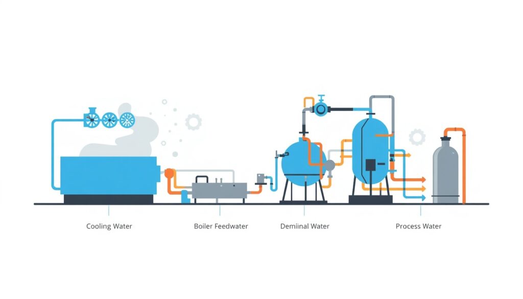
    The Main Water Systems in an Industrial Plant

    Main water systems in an industrial plant diagram

    Main water systems in an industrial plant diagram

    Different plant systems have different water quality requirements.

    System Purpose Key Water Quality Concerns
    Cooling water Reject heat from condensers and auxiliary equipment Scaling, corrosion, biological growth
    Boiler feedwater Produce steam in boilers Scale, corrosion, carryover
    Demineralized water Feed high-pressure boilers and process systems Dissolved solids, silica, conductivity
    Process water Used in chemical or manufacturing processes Varies by process
    Potable water For human consumption and sanitation Microbial, chemical, and aesthetic standards

    Each system requires a different level of treatment. Cooling water typically needs less treatment than boiler feedwater, which must be nearly pure. Process water treatment depends on the specific process. Some processes require demineralized water, while others can tolerate lower quality.

    Key Water Quality Parameters

    Water treatment is designed to control specific parameters. These include:

    • Hardness: Calcium and magnesium ions that cause scaling.
    • Alkalinity: Bicarbonate and carbonate ions that affect pH and scaling potential.
    • pH: Acidity or alkalinity of the water.
    • Conductivity: Measure of dissolved solids.
    • Silica: Forms hard deposits on boiler and turbine surfaces.
    • Dissolved oxygen: Causes corrosion in boilers and cooling systems.
    • Iron and copper: Corrosion products that deposit on surfaces.
    • Chlorides: Cause pitting corrosion in stainless steels.
    • Suspended solids: Cause fouling and deposits.
    • Microorganisms: Cause biofilms and microbiologically influenced corrosion.

    Cooling Water Treatment

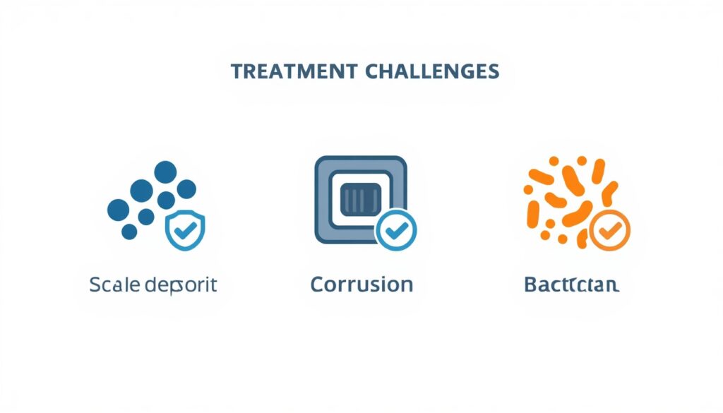
    Cooling water treatment challenges including scaling, corrosion, and biological growth

    Cooling water treatment challenges including scaling, corrosion, and biological growth

    Cooling water treatment focuses on three main problems: scaling, corrosion, and biological growth. Treatment requirements also depend heavily on the type of cooling system used.

    Scaling control:

    Scale forms when dissolved minerals precipitate on heat transfer surfaces. The most common scale is calcium carbonate, but calcium sulfate, silica, and other deposits also occur.

    Control methods include:

    • Chemical inhibitors: Phosphonates, polymers, and other chemicals that prevent crystal formation.
    • pH control: Adjusting pH to keep minerals soluble.
    • Blowdown: Removing a portion of recirculating water to control dissolved solids concentration.
    • Softening: Removing hardness ions before they enter the system.

    Corrosion control:

    Corrosion in cooling systems is caused by dissolved oxygen, low pH, chlorides, and microbiological activity.

    Control methods include:

    • Corrosion inhibitors: Chemicals that form protective films on metal surfaces.
    • pH control: Maintaining pH in a range that minimizes corrosion.
    • Material selection: Using corrosion-resistant materials where needed.
    • Cathodic protection: For critical components.

    Biological control:

    Bacteria, algae, and fungi grow in cooling systems, especially in warm water with nutrients.

    Control methods include:

    • Biocides: Oxidizing (chlorine, bromine) or non-oxidizing chemicals that kill microorganisms.
    • Dispersants: Chemicals that break up biofilms.
    • Physical cleaning: Periodic flushing or mechanical cleaning.

    Once-through cooling systems:

    Once-through cooling systems require less chemical treatment than closed-loop systems because water is not recirculated. However, intake screening, chlorination, and corrosion control may still be required.

    Air-cooled systems:

    Plants using air-cooled cooling systems eliminate cooling water treatment, but boiler water treatment and demineralized water production may still be required.

    Boiler Water Treatment

    Boiler water treatment is more demanding than cooling water treatment because boilers operate at high temperature and pressure.

    External treatment:

    External treatment removes impurities before water enters the boiler. Common processes include:

    • Clarification: Removing suspended solids.
    • Filtration: Removing fine particles.
    • Softening: Removing hardness ions.
    • Demineralization: Removing all dissolved solids using ion exchange.
    • Reverse osmosis: Removing dissolved solids using membrane filtration.

    Internal treatment:

    Internal treatment controls residual impurities inside the boiler. Common chemicals include:

    • Oxygen scavengers: Remove dissolved oxygen.
    • pH adjusters: Maintain alkaline pH to minimize corrosion.
    • Scale inhibitors: Prevent precipitation on boiler surfaces.
    • Anti-foaming agents: Prevent foaming and carryover.

    Blowdown:

    Blowdown removes a portion of boiler water to control dissolved solids concentration. Continuous blowdown is preferred for larger boilers; intermittent blowdown is used for smaller ones.

    Demineralized Water Production

    High-pressure boilers and some process systems require demineralized water, which is water with almost all dissolved solids removed.

    Common demineralization processes include:

    • Ion exchange: Uses resins to exchange dissolved ions for hydrogen and hydroxide ions.
    • Reverse osmosis: Uses pressure to force water through a semi-permeable membrane, leaving dissolved solids behind.
    • Electrodeionization (EDI): Combines ion exchange and membrane processes for continuous demineralization.

    Demineralized water is essential for high-pressure boilers because dissolved solids can deposit on turbine blades, causing imbalance and efficiency loss.

    Key Design Considerations

    1. Water Source and Quality — The first step in water treatment design is understanding the water source. Surface water, groundwater, seawater, and municipal water all have different characteristics and require different treatment.
    2. Treatment Goals — Treatment goals depend on the end use. Cooling water, boiler feedwater, and demineralized water each have different quality requirements.
    3. Chemical Storage and Handling — Water treatment chemicals must be stored and handled safely. This requires appropriate containment, ventilation, and personal protective equipment. Personnel handling water treatment chemicals must be trained in safe handling, emergency response, and proper use of personal protective equipment.
    4. Waste Streams — Water treatment produces waste streams, including blowdown, filter backwash, and regeneration waste. These must be managed in compliance with environmental regulations.
    5. Monitoring and Control — Water quality must be monitored continuously. Key parameters include pH, conductivity, hardness, silica, and dissolved oxygen. Automated control systems help maintain treatment within specified limits.
    6. Redundancy — Critical water treatment components (pumps, resin beds, membrane units) may require redundancy to ensure continuous operation.

    Common Mistakes in Water Treatment

    Even experienced designers make mistakes. Common ones include:

    • Undersizing treatment systems: Leading to inadequate water quality and equipment damage.
    • Ignoring water source variability: Water quality changes seasonally and over time.
    • Insufficient chemical storage: Running out of treatment chemicals causes system upsets.
    • Poor waste management: Leading to environmental violations.
    • Inadequate monitoring: Failing to detect water quality excursions before damage occurs.
    • Skipping redundancy: A single point of failure can shut down the plant.

    These mistakes are costly to fix after construction. They are much cheaper to avoid during design.

    How Japanese EPC Firms Approach Water Treatment

    Japanese engineering firms are known for their disciplined approach to water treatment design. Common characteristics include:

    • Thorough water source assessment: Water quality is analyzed over time to capture variability.
    • Conservative design margins: Treatment systems are sized with adequate margin for worst-case water quality.
    • Detailed chemical management: Chemical selection, storage, and handling are carefully planned.
    • Comprehensive monitoring: Water quality is tracked continuously with clear alarm and response procedures.
    • Long-term performance focus: Treatment system performance is monitored and optimized over the plant’s life.

    For plant owners, this often means a water treatment system that performs reliably for decades, even under challenging water conditions.

    How to Evaluate Water Treatment Design

    When reviewing water treatment design, ask:

    Question Why It Matters
    What is the water source and quality? Determines treatment requirements
    What are the treatment goals for each system? Ensures water quality meets end-use requirements
    How is water quality monitored? Detects excursions before damage occurs
    How are chemicals stored and handled? Ensures safety and regulatory compliance
    How are waste streams managed? Ensures environmental compliance
    Is redundancy provided for critical components? Ensures continuous operation
    What is the life-cycle cost? Captures total cost, not just capital

    A water treatment system that addresses these questions is likely to perform well over the plant’s life.

    Key Takeaways

    • Water treatment controls corrosion, scaling, fouling, and biological growth
    • Different plant systems have different water quality requirements
    • Cooling water treatment focuses on scaling, corrosion, and biological control
    • Boiler water treatment is more demanding and requires external and internal treatment
    • Demineralized water is essential for high-pressure boilers
    • Japanese EPC firms emphasize thorough water source assessment and conservative design margins

    Conclusion

    Water treatment is a critical but often overlooked aspect of industrial plant design. It affects reliability, efficiency, maintenance cost, and environmental compliance. For small to medium-scale industrial plants, where margins are tight, water treatment deserves careful attention from the earliest stages of design.
    By understanding water quality requirements, selecting appropriate treatment processes, and planning for monitoring, redundancy, and waste management, owners and designers can ensure reliable water quality and long-term plant performance.

  • Cooling Systems for Industrial Plants: Options and Trade-Offs

    Cooling Systems for Industrial Plants: Options and Trade-Offs

    Cooling is one of the most overlooked yet consequential decisions in industrial plant design. Every thermal plant—whether it burns coal, gas, biomass, or waste heat—must reject heat to the environment. How that heat is rejected affects efficiency, water consumption, environmental impact, capital cost, and site selection.

    For small to medium-scale industrial plants, cooling system selection is especially critical because there is less margin for error and fewer resources to manage complex systems. The wrong choice can limit plant output, increase operating cost, or create regulatory problems.

    This article covers the main cooling system options, compares them side by side, and helps you decide which one fits your project.

    Why Cooling Matters

    Thermal plants convert heat into electricity, but not all heat can be converted. A significant portion must be rejected to the environment. This is a fundamental thermodynamic limit—no plant can convert all its heat input into useful work.

    The cooling system’s job is to reject this waste heat efficiently and reliably. The main functions are:

    • Condensing steam: In steam cycles, cooling condenses the exhaust steam from the turbine back into water so it can be reused.
    • Cooling auxiliary equipment: Lubricating oil, generators, and other equipment require cooling.
    • Maintaining vacuum: Efficient condensing requires low pressure, which depends on effective cooling.

    If the cooling system underperforms, the turbine back pressure rises, reducing output and efficiency. In severe cases, the plant must reduce load or shut down.

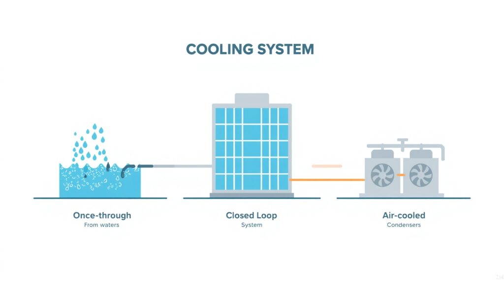
    The Main Cooling System Options

    Comparison of once-through, closed-loop, and air-cooled cooling system types

    Comparison of once-through, closed-loop, and air-cooled cooling system types

    There are three main types of cooling systems for industrial plants:

    1. Once-through cooling
    2. Closed-loop (recirculating) cooling with cooling towers
    3. Air-cooled (dry) cooling

    Each has distinct characteristics, advantages, and drawbacks.

    Once-Through Cooling

    In a once-through system, water is drawn from a nearby source (river, lake, sea), passed through the condenser, and returned to the source at a higher temperature.

    Characteristics:

    • High efficiency: Once-through cooling provides the best cooling performance because water temperature is typically low.
    • Low capital cost: Fewer components, simpler system.
    • High water consumption: Large volumes of water are drawn and returned.
    • Environmental impact: Thermal discharge can affect aquatic ecosystems.
    • Site constraint: Requires a large, reliable water source.

    When it makes sense:

    • Sites with access to abundant cooling water (coastal or large river locations)
    • Regions with lenient thermal discharge regulations
    • Plants where efficiency is the top priority

    Once-through cooling is increasingly restricted in many jurisdictions due to environmental concerns. In the United States, for example, the Clean Water Act Section 316(b) requires that cooling water intake structures minimize environmental impact.

    Closed-Loop Cooling with Cooling Towers

    In a closed-loop system, cooling water is recirculated between the condenser and a cooling tower. The cooling tower rejects heat to the atmosphere, primarily through evaporation.

    Characteristics:

    • Moderate efficiency: Performance depends on ambient wet-bulb temperature. Efficiency is lower than once-through but higher than air-cooled.
    • Moderate capital cost: Cooling towers and circulating water systems add cost.
    • Lower water consumption: Water is lost primarily through evaporation and blowdown, but consumption is much lower than once-through.
    • Visible plume: Cooling towers produce a visible plume of water vapor, which can be a concern in some locations.
    • Chemical treatment: Recirculated water requires treatment to control corrosion, scaling, and biological growth. Closed-loop systems require continuous water treatment to manage these effects; treatment programs typically include corrosion inhibitors, scale inhibitors, and biocides.

    When it makes sense:

    • Sites with limited water availability
    • Regions with strict thermal discharge regulations
    • Plants where a balance between efficiency and water use is needed

    Closed-loop cooling is the most common choice for new industrial plants in many regions. It offers a reasonable compromise between efficiency, water use, and environmental impact.

    Air-Cooled (Dry) Cooling

    In an air-cooled system, heat is rejected directly to the atmosphere using air-cooled condensers or fin-fan coolers. No cooling water is used.

    Characteristics:

    • Lower efficiency: Performance depends on ambient dry-bulb temperature, which is typically higher than wet-bulb temperature. This reduces plant efficiency compared to wet cooling.
    • Higher capital cost: Air-cooled condensers are large and expensive.
    • Zero water consumption: No cooling water is required for heat rejection.
    • Large footprint: Air-cooled systems require significant space.
    • Higher auxiliary power: Fans consume more power than cooling tower fans.

    When it makes sense:

    • Sites with no reliable water source
    • Regions with strict water use restrictions
    • Plants where water availability is uncertain or expensive

    Air-cooled cooling is common in arid regions and in plants where water is scarce or expensive. It eliminates water consumption but at the cost of efficiency and capital cost.

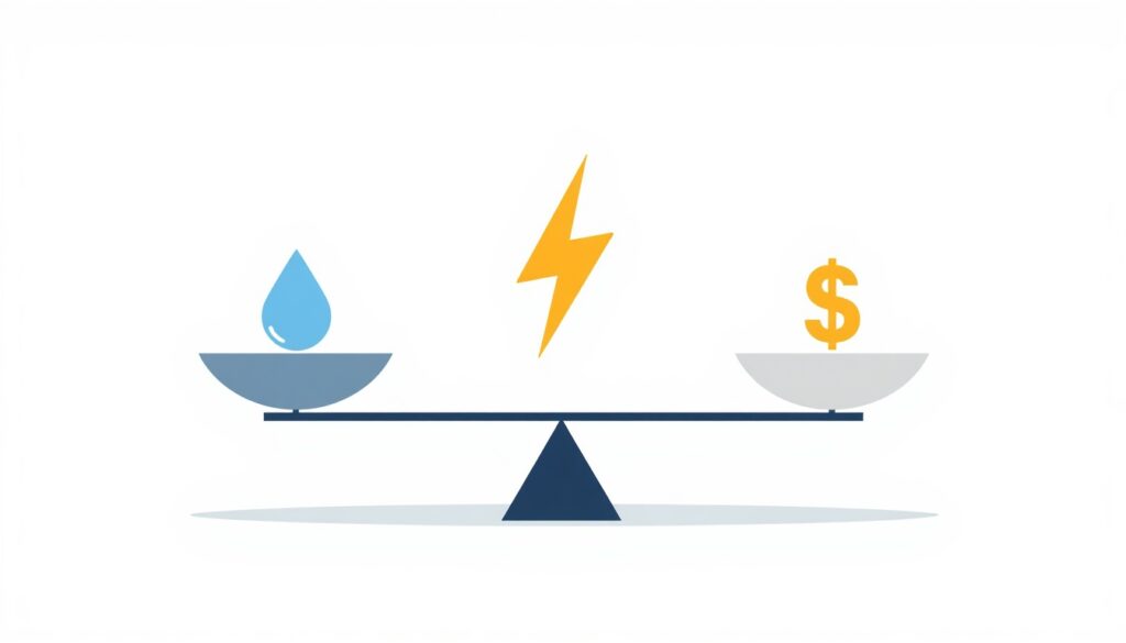
    Side-by-Side Comparison

    Trade-offs between water consumption, efficiency, and capital cost in cooling systems

    Trade-offs between water consumption, efficiency, and capital cost in cooling systems

    Factor Once-Through Closed-Loop (Wet) Air-Cooled (Dry)
    Cooling efficiency Highest Moderate Lowest
    Capital cost Lowest Moderate Highest
    Water consumption Highest Moderate None
    Footprint Small Moderate Large
    Auxiliary power Lowest Moderate Highest
    Environmental impact Thermal discharge Water consumption, plume Land use, noise
    Site requirement Large water source Moderate water source No water source
    Typical use Coastal, large rivers Most inland plants Arid regions

    Hybrid Cooling Systems

    Some plants use hybrid cooling, which combines wet and dry cooling. In a hybrid system, cooling towers operate during cooler periods, while air-cooled condensers take over during peak heat or when water is scarce.

    Advantages:

    • Reduces water consumption compared to pure wet cooling
    • Improves efficiency compared to pure dry cooling
    • Provides flexibility to respond to water availability and ambient conditions

    Disadvantages:

    • Higher capital cost than either pure wet or pure dry
    • More complex operation and maintenance

    Hybrid cooling is often used in regions with seasonal water constraints or where a balance between efficiency and water use is required.

    Key Design Considerations

    1. Ambient Conditions

    Wet-bulb temperature drives wet cooling performance. Dry-bulb temperature drives air-cooled performance. Both vary by location and season. Design must account for the worst-case conditions the plant will face.

    2. Water Availability and Quality

    Water quantity, quality, and cost all affect cooling system selection. Poor water quality may require treatment, which adds cost and complexity.

    3. Environmental Regulations

    Thermal discharge limits, water intake rules, and plume restrictions can all constrain cooling system options. These must be identified early in design.

    4. Plant Size and Load Profile

    Small plants may have different constraints than large ones. A plant that operates only during peak hours may not justify the cost of a complex cooling system.

    5. Parasitic Power

    Cooling system auxiliaries (pumps, fans) consume power, reducing net plant output. This must be accounted for in performance calculations.

    6. Corrosion and Materials

    Cooling water chemistry affects material selection. Once-through systems using seawater require corrosion-resistant materials. Closed-loop systems require water treatment to control scaling and corrosion.

    7. Availability and Redundancy

    For critical plants, consider whether redundancy in cooling system components (pumps, fans, cells) is justified. A single cooling tower cell failure can limit plant output.

    8. Noise Regulations

    Noise from cooling towers and air-cooled condensers can be a constraint in populated areas. Local noise regulations may limit fan speed or require acoustic treatment.

    9. Control and Optimization

    Modern cooling systems use variable frequency drives and advanced controls to match cooling output to plant load and ambient conditions. This reduces auxiliary power consumption at part load.

    Common Mistakes in Cooling System Selection

    Even experienced designers make mistakes. Common ones include:

    • Underestimating water consumption: Especially for wet cooling in water-scarce regions
    • Ignoring ambient extremes: Designing for average conditions rather than worst-case
    • Overlooking regulations: Discovering too late that thermal discharge or intake rules prohibit the chosen system
    • Undersizing cooling towers: Leading to higher back pressure and reduced output
    • Neglecting auxiliary power: Forgetting that fans and pumps reduce net output
    • Poor water treatment: Leading to scaling, corrosion, and reduced performance

    These mistakes are costly to fix after construction. They are much cheaper to avoid during design.

    How Japanese EPC Firms Approach Cooling System Selection

    Japanese engineering firms are known for their disciplined approach to cooling system design. Common characteristics include:

    • Thorough site assessment: Water availability, ambient conditions, and regulations are studied carefully before selection.
    • Conservative design margins: Cooling systems are sized with adequate margin for worst-case conditions.
    • Life-cycle cost focus: Capital cost is evaluated alongside operating cost, water cost, and environmental compliance.
    • Detailed water treatment design: Water chemistry is managed carefully to ensure long-term reliability.
    • Long-term performance monitoring: Cooling system performance is tracked over the plant’s life.

    For plant owners, this often means a cooling system that performs reliably for decades, even under challenging conditions.

    How to Evaluate Cooling System Options

    When reviewing cooling system options, ask:

    Question Why It Matters
    What is the ambient design condition? Determines cooling performance and system size
    Is water available, and at what cost? Affects selection and operating cost
    What are the environmental regulations? Constrains system options
    What is the auxiliary power consumption? Reduces net plant output
    What is the life-cycle cost? Captures total cost, not just capital
    How reliable is the system? Affects plant availability
    How complex is operation and maintenance? Affects staffing and long-term cost

    A cooling system that satisfies all these questions is likely to perform well over the plant’s life.

    Key Takeaways

    • Cooling system selection affects efficiency, water use, cost, and environmental impact
    • Once-through: highest efficiency, highest water use
    • Closed-loop: moderate efficiency, moderate water use
    • Air-cooled: lowest efficiency, zero water use
    • Hybrid systems balance wet and dry cooling
    • Japanese EPC firms emphasize thorough site assessment and conservative design margins

    Conclusion

    Cooling system selection is a strategic decision that affects efficiency, water consumption, environmental impact, and cost. Once-through, closed-loop, and air-cooled systems each have distinct advantages and drawbacks. For small to medium-scale industrial plants, the right choice depends on site conditions, water availability, regulations, and financial objectives.

    By evaluating these factors carefully and considering life-cycle cost, owners and designers can select a cooling system that performs reliably and economically for decades.

  • HRSG Design and Operation: Key Considerations for Combined Cycle Plants

    HRSG Design and Operation: Key Considerations for Combined Cycle Plants

    The heat recovery steam generator (HRSG) is the component that makes combined cycle power generation possible. Without it, the hot exhaust gas from the gas turbine would be wasted, and the plant would operate as a simple cycle with much lower efficiency.

    For plant owners and engineers working with combined cycle plants, understanding HRSG design and operation is essential. The HRSG determines how much additional electricity the plant can produce, how quickly it can respond to load changes, and how reliably it operates over its life.

    This article covers the fundamentals of HRSG design, the key configuration options, operational considerations, and common issues that plant owners should be aware of.

    What Is an HRSG?

    An HRSG is a heat exchanger that recovers heat from the gas turbine exhaust and uses it to produce steam. That steam then drives a steam turbine to generate additional electricity.

    The basic flow is:

    • Gas turbine exhaust enters the HRSG
    • Heat is transferred to water and steam in tubes
    • Steam is produced at one or more pressure levels
    • Steam drives the steam turbine
    • Exhaust gas exits the HRSG at a much lower temperature

    The HRSG is essentially a boiler that has no burner of its own. All its heat comes from the gas turbine exhaust.

    Why the HRSG Matters

    The HRSG is the key to combined cycle efficiency. In a simple cycle plant, exhaust gas leaves the gas turbine at 500–600°C and is released to the atmosphere. In a combined cycle plant, that same exhaust gas passes through the HRSG, where its heat is used to generate steam.

    The result is that the plant produces significantly more electricity from the same fuel. This is why combined cycle plants achieve 50–60% efficiency, while simple cycle plants achieve only 30–40%.

    The HRSG also affects:

    • Plant output: More steam production means more electricity from the steam turbine.
    • Plant flexibility: HRSG design influences how quickly the plant can start and change load.
    • Plant reliability: HRSG failures can shut down the entire combined cycle plant.
    • Maintenance cost: HRSG components are subject to corrosion, fouling, and thermal fatigue.

    HRSG Configurations

    HRSG pressure level configurations comparison

    HRSGs come in several configurations, each suited to different applications.

    Horizontal vs. Vertical

    Configuration Characteristics Typical Use
    Horizontal Exhaust gas flows horizontally through the HRSG Large combined cycle plants
    Vertical Exhaust gas flows vertically upward Smaller plants, limited footprint

    Horizontal HRSGs are more common in large plants because they are easier to maintain and can accommodate larger tube bundles. Vertical HRSGs are more compact and are sometimes used in smaller installations.

    Number of Pressure Levels

    HRSGs can produce steam at one, two, or three pressure levels.

    Configuration Characteristics Efficiency Impact
    Single pressure Simplest design, one steam drum Lower efficiency, lower cost
    Dual pressure Two steam drums, two pressure levels Moderate efficiency, moderate cost
    Triple pressure Three steam drums, three pressure levels Highest efficiency, highest cost

    Triple pressure HRSGs extract more heat from the exhaust gas and produce more steam, improving overall plant efficiency. However, they are more complex and more expensive.

    For small to medium-scale plants, dual pressure is often a practical compromise between efficiency and cost. Triple pressure adds cost and complexity that may not be justified at smaller scales, while single pressure leaves efficiency on the table.

    Duct Firing

    Some HRSGs include supplementary firing (duct firing) to increase steam production. This increases plant output but reduces efficiency because it adds fuel without recovering additional waste heat. Duct firing also increases NOx emissions, which is a relevant consideration for plants in regulated jurisdictions.

    Duct firing is useful for meeting peak demand but is not typically used for baseload operation.

    Bypass Stacks

    Some HRSGs include a bypass stack that allows the gas turbine to operate independently when the steam cycle is unavailable, which adds flexibility during startup and when the steam side is out of service.

    Key Design Considerations

    1. Pinch Point and Approach Temperature

    The pinch point is the temperature difference between the exhaust gas leaving the evaporator and the saturated steam temperature. The approach temperature is the difference between the saturated steam temperature and the feedwater temperature entering the evaporator.

    Smaller pinch and approach temperatures mean more heat is recovered, improving efficiency. However, they also require larger heat transfer surfaces, increasing cost and footprint.

    Typical values:

    • Pinch point: 8–15°C
    • Approach temperature: 5–10°C

    2. Gas Side Pressure Drop

    The HRSG adds pressure drop to the exhaust gas path. Higher pressure drop reduces gas turbine output. Designers aim to minimize pressure drop while still achieving the required heat transfer.

    3. Tube Material Selection

    HRSG tubes are exposed to high temperatures and corrosive gases. Material selection depends on:

    • Exhaust gas temperature
    • Fuel composition (especially sulfur content)
    • Steam pressure and temperature
    • Expected operating hours

    Common materials include carbon steel for lower-temperature sections and alloy steels for higher-temperature sections.

    4. Drum Design and Sizing

    The steam drum separates steam from water and provides a buffer for load changes. Drum size affects the HRSG’s ability to handle rapid load changes and startup.

    5. Thermal Cycling

    HRSGs in cycling plants experience frequent thermal cycling, which causes fatigue in tubes, headers, and drums. Design must account for the expected number of cycles over the plant’s life.

    Operational Considerations

    Startup and Shutdown

    HRSG startup must be carefully controlled to avoid thermal stress. Key parameters include:

    • Drum heat-up rate
    • Tube metal temperature gradients
    • Steam temperature matching between HRSG and steam turbine

    Rapid startups increase thermal stress and can shorten component life.

    Water Chemistry

    Water quality is critical for HRSG reliability. Poor water chemistry leads to:

    • Scale formation on tubes
    • Corrosion of tube surfaces
    • Carryover of impurities into the steam turbine

    Water chemistry must be monitored continuously and controlled within strict limits.

    Fouling and Corrosion

    HRSG tubes can foul with deposits from exhaust gas, especially if the fuel contains sulfur or other impurities. Fouling reduces heat transfer and increases pressure drop, reducing plant efficiency.

    Corrosion can occur on the gas side (from acidic gases) or the water side (from poor water chemistry). Both must be managed through design, operation, and maintenance.

    Load Changes

    HRSGs respond to load changes more slowly than gas turbines. When the gas turbine load changes, the HRSG takes time to reach a new steady state. This affects the plant’s ability to respond to grid demand.

    Common HRSG Problems

    Even well-designed HRSGs can experience problems. Common issues include:

    • Tube failures: Caused by corrosion, fatigue, or overheating
    • Drum level instability: Caused by rapid load changes or poor control
    • Steam temperature excursions: Caused by changes in gas turbine load or exhaust temperature
    • Fouling and plugging: Caused by deposits from exhaust gas
    • Corrosion: Caused by acidic gases or poor water chemistry

    These problems can lead to reduced output, increased maintenance, and in severe cases, plant shutdown.

    How Japanese EPC Firms Approach HRSG Design

    Japanese engineering firms are known for their disciplined approach to HRSG design and operation. Common characteristics include:

    • Conservative design margins: Adequate pinch and approach temperatures, generous tube surface area
    • Careful material selection: Materials matched to fuel and operating conditions
    • Detailed thermal analysis: Startup and shutdown procedures designed to minimize thermal stress
    • Strict water chemistry control: Comprehensive monitoring and treatment programs
    • Long-term performance monitoring: Heat transfer and pressure drop tracked over the plant’s life

    For plant owners, this often means an HRSG that performs reliably for decades, even under cycling operation.

    How to Evaluate HRSG Design

    When reviewing an HRSG design, ask:

    Question Why It Matters
    What pinch and approach temperatures are specified? Determines efficiency and surface area
    How many pressure levels? Affects efficiency and complexity
    What materials are used for tubes? Determines resistance to corrosion and fatigue
    How is thermal cycling addressed? Affects component life in cycling plants
    What water chemistry limits apply? Determines reliability and maintenance needs
    How is fouling managed? Affects long-term performance
    What is the expected pressure drop? Affects gas turbine output

    A design that addresses these questions is likely to perform well over the plant’s life.

    Conclusion

    The HRSG is the heart of a combined cycle plant. It determines how much additional electricity the plant can produce and how efficiently it uses fuel. Understanding HRSG design and operation helps plant owners evaluate proposals, plan maintenance, and optimize performance.

    For small to medium-scale combined cycle plants, the HRSG is often the most technically complex component. Careful attention to design, materials, water chemistry, and operational procedures is essential for reliable, efficient operation over the plant’s life.

    Key Takeaways

    • The HRSG recovers gas turbine exhaust heat to produce steam, which is what lifts combined cycle efficiency well above simple cycle.
    • Configuration (horizontal or vertical, number of pressure levels) affects efficiency, cost, and complexity.
    • Pinch point and approach temperature are key design parameters, trading heat recovery against surface area and cost.
    • Water chemistry control and thermal cycling management are critical for long-term reliability.
  • Combined Cycle vs. Simple Cycle: Choosing the Right Configuration for Your Plant

    Combined Cycle vs. Simple Cycle: Choosing the Right Configuration for Your Plant

    When planning a thermal power plant, one of the first configuration decisions is whether to use a simple cycle or a combined cycle. This choice affects capital cost, efficiency, fuel consumption, emissions, and operational flexibility. For small to medium-scale industrial plants, the right choice depends on your load profile, fuel availability, site constraints, and financial objectives.

    This article explains the difference between simple cycle and combined cycle, compares them side by side, and helps you decide which configuration fits your project.

    Note on fuel: this article assumes natural gas throughout. Gas turbines can also run on liquid fuels such as distillate and on syngas. Simple cycle plants are generally more fuel-flexible, while combined cycle plants are most often gas-fired, with liquid fuel typically used only as backup.

    What Is a Simple Cycle Plant?

    A simple cycle plant uses a gas turbine to generate electricity directly. The turbine burns fuel, produces hot exhaust gas, and drives a generator. The exhaust gas is then released to the atmosphere.

    Simple cycle plants are:

    • Simple to design and build: Fewer components, shorter construction time.
    • Lower in capital cost: Less equipment, smaller footprint.
    • Fast to start: Can reach full load in minutes.
    • Less efficient: Typical efficiency of 30–40%.
    • Higher heat rate: More fuel consumed per unit of output.

    Simple cycle plants are often used for peaking power, backup generation, and remote locations where simplicity and speed matter more than efficiency.

    What Is a Combined Cycle Plant?

    A combined cycle plant uses both a gas turbine and a steam turbine to generate electricity. The gas turbine produces electricity, and its hot exhaust gas is directed to a heat recovery steam generator (HRSG). The HRSG produces steam, which drives a steam turbine to generate additional electricity.

    Combined cycle plants are:

    • More efficient: Typical efficiency of 50–60% or higher.
    • Lower heat rate: Less fuel consumed per unit of output.
    • Higher capital cost: More equipment, larger footprint.
    • Slower to start: Takes longer to reach full load.
    • More complex to design and operate.

    Combined cycle plants are often used for baseload power, where high efficiency and low fuel cost are priorities.

    The Key Difference

    Simple cycle versus combined cycle energy flow diagram

    The fundamental difference is waste heat recovery.

    In a simple cycle plant, the hot exhaust gas from the gas turbine is wasted. In a combined cycle plant, that heat is captured and used to generate additional electricity.

    This is why combined cycle plants achieve much higher efficiency. By recovering waste heat, they extract more useful energy from the same fuel.

    Side-by-Side Comparison

    Factor Simple Cycle Combined Cycle
    Efficiency 30–40% 50–60% or higher
    Heat rate Higher (more fuel per kWh) Lower (less fuel per kWh)
    Capital cost Lower Higher
    Footprint Smaller Larger
    Construction time Shorter Longer
    Startup time Fast (minutes) Slower (30–60 minutes hot start; several hours cold)
    Operational flexibility High Lower
    Emissions per kWh Higher Lower
    Typical use Peaking, backup Baseload, industrial
    Sensitivity to fuel price High Lower

    When Simple Cycle Makes Sense

    Simple cycle is often the right choice when:

    • Capital cost is the primary constraint. If budget is limited, simple cycle requires less upfront investment.
    • The plant operates infrequently. Peaking plants that run only a few hundred hours per year do not benefit much from higher efficiency.
    • Fast startup is critical. Simple cycle plants can reach full load in minutes, making them ideal for grid support.
    • The site is remote or constrained. Smaller footprint and simpler infrastructure reduce site requirements.
    • Fuel is cheap or subsidized. If fuel cost is low, the efficiency penalty of simple cycle matters less.
    • The project needs to be built quickly. Shorter construction time can be a decisive advantage.

    When Combined Cycle Makes Sense

    Combined cycle is often the right choice when:

    • The plant operates frequently. Baseload or industrial plants that run thousands of hours per year benefit greatly from higher efficiency.
    • Fuel cost is significant. Lower heat rate translates directly into lower operating cost.
    • Emissions limits are tight. Combined cycle produces less CO₂ and other emissions per kWh.
    • Long-term economics matter more than upfront cost. Higher capital cost is recovered through fuel savings over the plant’s life.
    • The site can accommodate a larger plant. Combined cycle requires more space for the HRSG, steam turbine, and cooling systems.
    • The load profile is stable. Combined cycle plants perform best when operating at steady, high load.

    The Economics of Combined Cycle

    Economics comparison of combined cycle and simple cycle power plants

    The higher capital cost of combined cycle is justified by fuel savings over the plant’s life. The payback period depends on:

    • Fuel cost: Higher fuel cost favors combined cycle.
    • Operating hours: More hours per year favor combined cycle.
    • Load factor: Higher average load favors combined cycle.
    • Capital cost premium: A smaller gap between the two options shortens the payback. (If you evaluate NPV rather than simple payback, a lower discount rate also favors long-term savings.)

    A simplified, illustrative comparison for a 50 MW plant operating 8,000 hours per year at a fuel price of about $7.3/MMBtu:

    Parameter Simple Cycle Combined Cycle
    Capital cost $50 million $75 million
    Efficiency 35% 55%
    Fuel cost per year (at 8,000 hours) $28.6 million $18.2 million
    Annual fuel savings — $10.4 million
    Simple payback — ~2.4 years

    In this example, the additional $25 million capital cost is recovered in about 2.4 years through fuel savings. After that, the combined cycle plant saves over $10 million per year, before accounting for its higher maintenance costs.

    Note that 8,000 hours per year is close to baseload operation. At 2,000 hours per year, annual fuel savings fall to roughly $2.6 million and the payback stretches to roughly 10 years, which makes simple cycle considerably more attractive. This simple payback also excludes O&M and financing costs, which would lengthen both figures.

    Operational Considerations

    Beyond economics, simple cycle and combined cycle differ in operational characteristics.

    Startup and shutdown:

    • Simple cycle: Fast start, suitable for peaking and grid support.
    • Combined cycle: Slower start, less suitable for rapid load changes.

    Part-load efficiency:

    • Simple cycle: Efficiency drops significantly at part load.
    • Combined cycle: Efficiency also drops at part load, but less steeply.

    Maintenance:

    • Simple cycle: Fewer components, simpler maintenance.
    • Combined cycle: More components, including HRSG and steam turbine, requiring more maintenance.

    Reliability:

    • Simple cycle: Fewer systems, potentially higher reliability.
    • Combined cycle: More systems, but redundancy can be built in.

    For small plants, operational simplicity may be more valuable than maximum efficiency. This is a key trade-off to consider.

    Environmental Considerations

    Combined cycle plants produce less CO₂ per kWh because they consume less fuel. NOx emissions per kWh are also lower, mainly because higher efficiency means less exhaust per unit of output, although both configurations need appropriate combustion controls or exhaust treatment to meet permit limits. Combined cycle is also generally better suited to future post-combustion carbon capture, since the HRSG and steam system can supply the heat needed for solvent regeneration and higher operating hours better justify the investment.

    For plants subject to strict emissions regulations or carbon pricing, combined cycle is often the more practical option. For plants in regions with lax emissions rules and cheap fuel, simple cycle may be acceptable.

    How Japanese EPC Firms Approach This

    Japanese engineering firms often favor combined cycle for industrial plants where efficiency and long-term operating cost matter. Common characteristics include:

    • Life-cycle cost focus: Combined cycle is evaluated on total cost, not just capital cost.
    • Conservative design: Adequate margins for fuel variation and ambient conditions.
    • Detailed performance testing: Heat rate and output guarantees are carefully verified.
    • Long-term support: Ongoing monitoring and optimization after commissioning.
    • Emissions compliance: Designs that meet or exceed environmental standards.

    For plant owners, this often means a configuration that delivers low operating cost and reliable performance over decades.

    How to Decide

    Ask yourself these questions:

    Question If Yes If No
    Will the plant operate more than 4,000 hours per year? (rule of thumb; depends on fuel price) Combined cycle Simple cycle
    Is fuel cost a major concern? Combined cycle Simple cycle
    Is capital cost the primary constraint? Simple cycle Combined cycle
    Is fast startup critical? Simple cycle Combined cycle
    Are emissions limits tight? Combined cycle Simple cycle
    Is the site large enough for combined cycle? Combined cycle Simple cycle
    Is long-term economics more important than upfront cost? Combined cycle Simple cycle

    For most small to medium-scale industrial plants that operate frequently, combined cycle is the better choice. For peaking plants or sites with tight constraints, simple cycle may be more appropriate.

    Conclusion

    Simple cycle and combined cycle are both valid configurations for thermal power plants. Simple cycle offers lower capital cost, faster startup, and simpler operation. Combined cycle offers higher efficiency, lower fuel cost, and lower emissions.

    The right choice depends on your load profile, fuel cost, site constraints, and financial objectives. By evaluating these factors carefully, you can select the configuration that delivers the best long-term value for your plant.

    Key Takeaways

    • Simple cycle: lower capital cost, faster start, lower efficiency.
    • Combined cycle: higher capital cost, higher efficiency, lower fuel cost per kWh.
    • Choose combined cycle for frequent operation and high fuel cost.
    • Choose simple cycle for peaking duty, remote sites, or tight budgets.
  • Understanding Heat Rate and Thermal Efficiency in Industrial Plants

    Understanding Heat Rate and Thermal Efficiency in Industrial Plants

    Heat rate is one of the most important performance metrics in thermal power generation. It measures how efficiently a plant converts fuel into electricity. For plant owners, heat rate directly affects operating cost, fuel consumption, and profitability.

    Despite its importance, heat rate is often misunderstood. It is sometimes confused with thermal efficiency, and its relationship to fuel cost is not always clear. This article explains what heat rate is, how it is calculated, what affects it, and why it matters for small to medium-scale industrial plants.

    What Is Heat Rate?

    Heat rate energy input and output illustration

    Heat rate is the amount of energy input required to produce one unit of energy output. In power generation, it is typically expressed in kJ/kWh (kilojoules per kilowatt-hour) or Btu/kWh (British thermal units per kilowatt-hour). To convert between them, 1 kJ/kWh ≈ 0.948 Btu/kWh (equivalently, 1 Btu/kWh ≈ 1.055 kJ/kWh). This article uses kJ/kWh throughout.

    A lower heat rate means better efficiency. A higher heat rate means more fuel is required to produce the same output.

    For example:

    • A plant with a heat rate of 10,000 kJ/kWh requires 10,000 kJ of fuel energy to produce 1 kWh of electricity.
    • A plant with a heat rate of 8,000 kJ/kWh requires only 8,000 kJ of fuel energy to produce the same 1 kWh.

    The second plant is more efficient and will have lower fuel costs for the same output.

    One caution on the fuel side: heat rate can be based on the fuel’s lower heating value (LHV) or higher heating value (HHV). HHV-based figures are higher (worse) than LHV-based figures for the same plant, by roughly 10% for natural gas and less for coal. Always confirm which basis is being used before comparing numbers.

    Heat Rate vs. Thermal Efficiency

    Heat rate and thermal efficiency are related but not identical. Thermal efficiency is the ratio of useful output to energy input, expressed as a percentage.

    The relationship is:

    Thermal Efficiency (%) = 3,600 / Heat Rate (kJ/kWh) × 100 (3,600 kJ = 1 kWh)

    The 3,600 is simply the number of kilojoules in one kilowatt-hour, that is, the energy content of one unit of electrical output. In Btu units, the equivalent constant is 3,412 Btu = 1 kWh.

    For example:

    • Heat rate of 10,000 kJ/kWh → efficiency = 36%
    • Heat rate of 8,000 kJ/kWh → efficiency = 45%
    • Heat rate of 12,000 kJ/kWh → efficiency = 30%

    In simple terms:

    • Lower heat rate = higher efficiency
    • Higher heat rate = lower efficiency

    Both metrics describe the same thing from different angles. Heat rate is preferred in some regions and industries; thermal efficiency is preferred in others.

    Why Heat Rate Matters

    Heat rate matters because fuel is the largest operating cost for most thermal plants. A small improvement in heat rate can translate into significant savings over the plant’s life.

    Consider a plant that consumes fuel at a cost of $5 per million kJ (equivalent to $5/GJ, or roughly $5.3/MMBtu). Fuel prices vary widely by region and over time, so the absolute numbers below are illustrative; substitute your own fuel contract price.

    Heat Rate (kJ/kWh) Fuel Cost per kWh Annual Fuel Cost (100 MW plant, full load, 8,760 h/year)
    12,000 $0.060 $52.6 million
    10,000 $0.050 $43.8 million
    8,000 $0.040 $35.0 million

    The difference between a heat rate of 12,000 and 8,000 is about $17.5 million per year for a 100 MW plant running continuously at full output. For smaller plants, the absolute numbers are lower, but the percentage impact is the same.

    This is why heat rate is often a key performance guarantee in EPC contracts. If the plant does not meet its guaranteed heat rate, the contractor may be liable for liquidated damages.

    For context, guarantee values depend on plant type, size, and the basis used (LHV or HHV, gross or net). For combined cycle plants, guarantees typically range from 6,000 to 7,500 kJ/kWh. For simple cycle plants, 9,000 to 12,000 kJ/kWh is common. Smaller plants tend toward the upper end of these ranges or above them.

    What Affects Heat Rate?

    Many factors influence a plant’s heat rate. Some are design-related, others are operational.

    Design factors:

    • Cycle configuration: Combined cycle plants have lower heat rates than simple cycle plants.
    • Equipment efficiency: Turbine, boiler, and generator efficiency all affect heat rate.
    • Steam conditions: Higher temperature and pressure improve efficiency.
    • Condenser performance: Better vacuum improves efficiency.
    • Auxiliary power consumption: Pumps, fans, and controls consume power, increasing net heat rate.

    Operational factors:

    • Load level: Plants are usually most efficient at or near full load.
    • Ambient conditions: Higher ambient temperature reduces output and increases heat rate.
    • Fuel quality: Lower heating value or impurities can reduce efficiency.
    • Equipment degradation: Fouling, wear, and leaks increase heat rate over time.
    • Operational practices: Startup, shutdown, and part-load operation affect average heat rate.

    For small plants, operational factors often have a larger impact because there is less design margin.

    Gross vs. Net Heat Rate

    Heat rate can be expressed as gross or net.

    • Gross heat rate: Based on total generator output, before subtracting auxiliary power consumption.
    • Net heat rate: Based on net output delivered to the grid, after subtracting auxiliary power.

    Net heat rate is always higher (worse) than gross heat rate because auxiliary equipment consumes power. For plant owners, net heat rate is the more relevant metric because it reflects the actual output available for sale.

    A common mistake is to compare gross heat rates from different plants without adjusting for auxiliary power. Always confirm which basis is being used.

    How Heat Rate Is Measured

    Heat rate is determined through performance testing, typically conducted after commissioning. The test measures:

    • Fuel input: Flow rate and heating value of fuel
    • Power output: Gross and net electrical output
    • Auxiliary power: Consumption of pumps, fans, and other equipment
    • Ambient conditions: Temperature, pressure, and humidity

    International standards such as ASME PTC 46 (overall plant performance) or ISO 2314 (gas turbines) provide procedures for conducting and reporting these tests. The results are used to verify contractual performance guarantees.

    Improving Heat Rate

    Heat rate can be improved through both design and operational measures.

    Design improvements:

    • Higher steam conditions: Supercritical or ultra-supercritical cycles (mainly practical for large utility-scale plants)
    • Combined cycle: Recovering waste heat from exhaust gases
    • Better condensers: Lower condenser pressure improves efficiency
    • Efficient auxiliaries: Variable frequency drives, high-efficiency motors
    • Advanced controls: Optimizing combustion and load allocation

    Operational improvements:

    • Operating at design point: Running at or near full load
    • Regular maintenance: Cleaning heat exchangers, repairing leaks, replacing worn components
    • Fuel management: Using consistent, high-quality fuel
    • Performance monitoring: Tracking heat rate trends to detect degradation
    • Operator training: Ensuring best practices for startup, shutdown, and load changes

    For existing plants, operational improvements often provide the fastest payback. For new plants, design improvements are built in from the start.

    Common Mistakes in Heat Rate Management

    Even experienced operators make mistakes. Common ones include:

    • Ignoring auxiliary power: Focusing on gross heat rate instead of net
    • Comparing at different conditions: Not correcting for ambient temperature or fuel quality
    • Neglecting degradation: Assuming heat rate stays constant over time
    • Operating at part load: Running at low load when full load is possible
    • Skipping performance tests: Not verifying heat rate after major overhauls
    • Poor fuel quality: Using inconsistent or low-quality fuel that increases heat rate

    These mistakes can lead to higher operating costs and missed performance targets.

    How Japanese EPC Firms Approach Heat Rate

    Japanese engineering firms are known for their focus on thermal efficiency. Common characteristics include:

    • Conservative design margins: Equipment is specified with enough margin to maintain performance over time.
    • Detailed performance testing: Heat rate tests are carefully planned and executed.
    • Long-term monitoring: Performance is tracked over the plant’s life, not just at commissioning.
    • Operational support: Japanese firms often provide ongoing support to help owners maintain efficiency.
    • Continuous improvement: Lessons from each project are applied to the next.

    For plant owners, this often means a plant that meets its heat rate guarantee and maintains performance over time.

    How to Evaluate Heat Rate Performance

    When reviewing heat rate performance, ask:

    Question Why It Matters
    Is the heat rate gross or net? Net heat rate reflects actual output for sale
    Is it based on LHV or HHV? The two bases differ by roughly 5–10%, depending on fuel
    What conditions apply? Heat rate varies with ambient temperature and fuel
    Has it been corrected to reference conditions? Allows comparison across different tests
    How has it changed over time? Detects degradation and maintenance needs
    How does it compare to the guarantee? Determines whether the contractor has met obligations
    What is the fuel cost impact? Translates heat rate into financial terms

    A plant that understands its heat rate performance can manage fuel costs, plan maintenance, and verify contractual compliance.

    Conclusion

    Heat rate is a fundamental measure of thermal plant efficiency. It directly affects fuel cost, operating profitability, and contractual performance. For small to medium-scale industrial plants, where margins are tight, understanding and managing heat rate is essential.

    By focusing on design efficiency, operational practices, and continuous monitoring, owners and operators can keep heat rate low and fuel costs under control.

    Key Takeaways

    • Heat rate measures fuel energy input per unit of electricity output.
    • Lower heat rate = higher efficiency.
    • Net heat rate reflects actual output for sale.
    • Heat rate is affected by design, operation, and ambient conditions.
    • Regular monitoring detects degradation and supports maintenance planning.
  • Equipment Selection Criteria for Small to Medium-Scale Industrial Plants

    Equipment Selection Criteria for Small to Medium-Scale Industrial Plants

    Equipment selection is one of the most consequential decisions in plant design. The equipment you choose determines capital cost, operating cost, reliability, maintenance requirements, and ultimately whether the plant meets its performance targets.

    For small to medium-scale industrial plants, equipment selection is especially critical. There is less redundancy, less margin for error, and less room to absorb the consequences of a poor choice. A pump that is oversized wastes energy for decades. A heat exchanger that is undersized limits output from day one.

    This article covers the key criteria that drive effective equipment selection for small to medium-scale plants. Whether you are specifying a boiler, a turbine, a pump, or a control system, these principles apply.

    Why Equipment Selection Matters More for Small Plants

    Large plants often have redundancy built into their designs. If one pump fails, a backup takes over. If one heat exchanger fouls, another compensates. Small plants rarely have this luxury.

    The consequences of poor equipment selection in a small plant include:

    • Higher capital cost: Oversized or over-specified equipment increases upfront investment.
    • Higher operating cost: Inefficient equipment consumes more fuel, power, or chemicals over its life.
    • Reduced reliability: Equipment that is marginal for the application fails more often.
    • Maintenance burden: Equipment that is difficult to service increases downtime and cost.
    • Limited flexibility: Equipment that cannot handle variations in load or feedstock restricts operations.

    For these reasons, equipment selection should be treated as a strategic decision, not a procurement formality.

    The Core Criteria for Equipment Selection

    Core criteria for industrial plant equipment selection

    A good equipment selection process evaluates each item against several criteria simultaneously:

    Criterion What It Means
    Technical suitability Does the equipment meet process requirements?
    Reliability How often does it fail, and how severe are failures?
    Efficiency How much energy, fuel, or consumable does it use?
    Capital cost What is the purchase price, including installation?
    Operating cost What are the ongoing costs of energy, maintenance, and spares?
    Maintainability How easy is it to inspect, repair, and replace?
    Lead time How long until delivery, and does it fit the schedule?
    Vendor support Does the supplier provide spares, service, and technical support?
    Compliance Does it meet codes, standards, and environmental requirements?

    These criteria sometimes conflict. A highly efficient piece of equipment may cost more upfront. A reliable vendor may have a longer lead time. Good selection balances these trade-offs.

    Technical Suitability

    The first question is always: does the equipment meet the process requirements?

    This includes:

    • Capacity: Can it handle the required flow, pressure, temperature, or load?
    • Range: Can it operate across the expected range of conditions?
    • Turndown: Can it operate stably and efficiently down to the minimum expected load?
    • Compatibility: Is it compatible with the process fluid, fuel, or environment?
    • Interfaces: Does it connect properly with upstream and downstream equipment?

    Manufacturers provide performance curves and datasheets that define these limits. These should be reviewed carefully, not assumed.

    A common mistake is selecting equipment that meets design conditions but performs poorly at off-design conditions. For small plants, which often operate across a wide range of loads, turndown and part-load efficiency are especially important.

    Equipment selection also directly affects whether the plant can meet its performance guarantees. If the plant must achieve a guaranteed heat rate or output, every major item must be capable of supporting it. A pump or heat exchanger that is marginal at design conditions may cause the entire plant to fall short. (See [title/link of article on performance guarantees].)

    Standardization vs. Customization

    For small plants, standard, off-the-shelf equipment is usually preferable to custom-designed units. Catalogue equipment typically costs less, is delivered faster, has a proven field record, and uses spare parts that are easier to source and interchange. Standardizing on the same models across the plant, such as a single pump family, also reduces the number of different spares to hold and simplifies operator training.

    Customization is justified when standard equipment cannot meet a process requirement or offers a clear performance advantage. Even then, its added cost, longer lead time, and heavier spares burden should be weighed explicitly rather than accepted by default.

    Reliability

    Reliability is the probability that equipment will perform its function without failure over a given period. For small plants, reliability is critical because there is often no redundancy.

    Key reliability considerations include:

    • Mean time between failures (MTBF): How often does the equipment fail?
    • Mean time to repair (MTTR): How long does it take to restore operation after a failure?
    • Failure mode: Does failure result in a safe shutdown or a hazardous condition?
    • Service history: How has this equipment performed in similar applications?

    Reliability data can come from manufacturer records, industry databases, or references from other plant owners. Do not rely solely on vendor claims.

    For critical equipment, consider whether redundancy is justified. A single spare pump may cost less than the production lost during a failure.

    Efficiency

    Efficiency determines how much energy or fuel the equipment consumes over its life. For equipment that runs continuously, efficiency often matters more than capital cost.

    Consider a pump, for example. Suppose it draws 100 kW and runs 8,000 hours per year at an electricity price of $0.10/kWh. Its annual energy cost is about $80,000. A pump that draws 5% less power saves about $4,000 per year, or roughly $40,000 over 10 years. If the more efficient pump carries a 20% price premium on a typical $20,000 unit, that premium is only $4,000, so it pays for itself in about one year. Even after discounting future savings (about $27,000 at an 8% discount rate), the energy savings far exceed the price difference.

    The same logic applies to boilers, turbines, compressors, and heat exchangers. The key is to evaluate life-cycle cost, not just purchase price.

    Capital Cost vs. Operating Cost

    Capital cost versus operating cost trade-off in equipment selection

    Equipment selection often involves a trade-off between capital cost and operating cost. A cheaper piece of equipment may consume more energy, require more maintenance, or fail more often.

    The tool for evaluating this trade-off is life-cycle cost analysis, also known as total cost of ownership (TCO) analysis. This sums:

    • Purchase price
    • Installation cost
    • Energy cost over the equipment’s life
    • Maintenance and spares cost
    • Downtime cost
    • Disposal or replacement cost

    For small plants, where margins are tight, life-cycle cost (TCO) is often the most important criterion. A slightly higher upfront investment in efficient, reliable equipment usually pays back many times over.

    Maintainability

    Maintainability considerations in industrial plant equipment selection

    Equipment must be maintainable. This means:

    • Access: Can it be reached for inspection and repair?
    • Disassembly: Can components be removed and replaced without major work?
    • Standardization: Are parts standard, or are they proprietary and slow to source?
    • Documentation: Are manuals, drawings, and procedures available?
    • Training: Can your team operate and maintain it, or is specialist support required?

    For small plants, maintainability is often overlooked. Equipment that is difficult to service leads to longer downtime, higher costs, and more reliance on external support.

    Lead Time and Schedule

    Lead time is the time between placing an order and receiving the equipment. For long-lead items such as turbines, generators, and large vessels, lead times can be 12 to 24 months or more.

    Lead time affects:

    • Project schedule: Long-lead items determine the critical path.
    • Procurement planning: Orders must be placed early enough to meet schedule.
    • Storage and preservation: Equipment delivered early must be stored and protected.
    • Vendor capacity: Popular vendors may be booked out for months.

    For small plants, lead time is often a constraint. Early identification of long-lead items allows procurement to start as soon as the design is firm.

    Vendor Support

    The equipment vendor is a partner for the life of the plant. Good vendor support includes:

    • Spare parts availability: Can parts be sourced quickly?
    • Technical support: Is help available when problems arise?
    • Warranty: What is covered, and for how long?
    • Service agreements: Are maintenance and overhaul services available?
    • Training: Does the vendor provide training for your team?

    A vendor with strong support may be worth a higher price. A vendor with poor support can leave you stranded when equipment fails.

    Spare Parts Strategy

    Availability from the vendor is only half the question. The other half is what to hold on site. For critical equipment, consider whether to stock spare parts on-site or rely on vendor delivery. Remote plants often justify carrying key spares, because a single missing part can idle the plant for weeks. A practical approach is to ask each vendor for a recommended spares list, then stock the items that are critical to operation, have long lead times, or are unlikely to be available locally. Weigh the carrying cost of these spares against the cost of downtime.

    Compliance and Standards

    Equipment must comply with applicable codes, standards, and regulations. These may include:

    • Pressure vessel codes: ASME, PED, or local equivalents
    • Electrical standards: IEC, NEC, or local equivalents
    • Environmental regulations: Emissions limits, noise limits, and discharge requirements
    • Safety standards: ATEX, NFPA, or local equivalents

    Compliance is not optional. Equipment that does not meet applicable standards cannot be legally operated, and may not be insurable.

    Common Equipment Selection Mistakes

    Even experienced designers make mistakes. Common ones include:

    • Selecting on price alone: Ignoring efficiency, reliability, and maintenance costs
    • Oversizing equipment: Adding unnecessary margin that increases cost and reduces efficiency
    • Undersizing equipment: Leaving no margin for actual operating conditions
    • Ignoring part-load performance: Optimizing for design point only
    • Overlooking lead time: Discovering too late that equipment cannot be delivered on schedule
    • Neglecting vendor support: Choosing a vendor with no local presence or spare parts
    • Skipping life-cycle cost analysis: Comparing only purchase prices

    These mistakes are costly to fix after equipment is installed. They are much cheaper to avoid during selection.

    How Japanese EPC Firms Approach Equipment Selection

    Japanese engineering firms are known for their disciplined approach to equipment selection. Common characteristics include:

    • Conservative sizing: Equipment is specified with adequate margin, but not excessive.
    • Emphasis on reliability: Proven equipment and vendors are preferred over untested alternatives.
    • Life-cycle cost focus: Purchase price is evaluated alongside operating and maintenance costs.
    • Long-term vendor relationships: Established vendors with strong support are favored.
    • Detailed documentation: Specifications, datasheets, and test records are carefully maintained.

    For plant owners, this often means equipment that performs reliably for decades, even if the initial price is higher than some alternatives.

    How to Evaluate Equipment Selection

    When reviewing equipment selections, ask:

    Question Why It Matters
    Does it meet process requirements? Ensures the plant can achieve its design output
    Can it support the performance guarantees? Prevents a marginal item from causing the plant to fall short
    Is it reliable? Reduces downtime and maintenance cost
    Is it efficient? Reduces operating cost over the plant’s life
    What is the life-cycle cost (TCO)? Captures total cost, not just purchase price
    Is it maintainable? Reduces downtime and reliance on external support
    Can it be delivered on schedule? Keeps the project on track
    Does the vendor provide good support, and are critical spares covered? Ensures spare parts and technical help are available
    Does it comply with standards? Ensures legal and safe operation

    A selection that satisfies all these questions is likely to perform well over the plant’s life.

    Conclusion

    Equipment selection is not just a procurement exercise. It is a strategic decision that affects cost, reliability, efficiency, and long-term performance. For small to medium-scale industrial plants, where margins are tight and redundancy is limited, equipment selection deserves careful attention from the earliest stages of design.
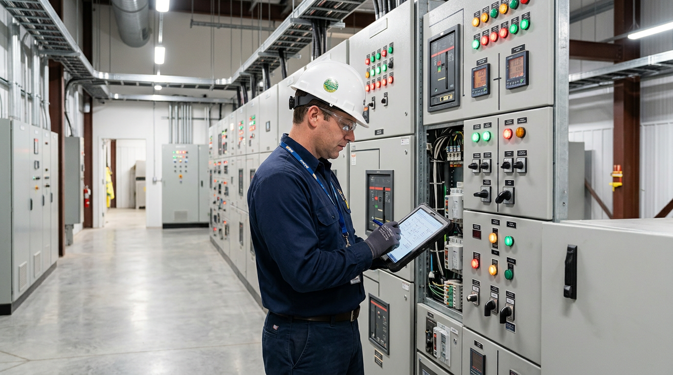
    By focusing on technical suitability, reliability, efficiency, life-cycle cost, maintainability, lead time, vendor support, and compliance, owners and designers can select equipment that performs reliably and economically for decades.

    Key Takeaways

    • Equipment selection affects cost, reliability, efficiency, and long-term performance.
    • Life-cycle cost (total cost of ownership), not just purchase price, should drive decisions.
    • Reliability and maintainability matter more in small plants with limited redundancy.
    • Standard, proven equipment and a sensible on-site spares strategy reduce cost, lead time, and downtime.
    • Lead time and vendor support are critical for schedule and long-term operation.
    • Japanese EPC firms favor conservative sizing, proven vendors, and detailed documentation.