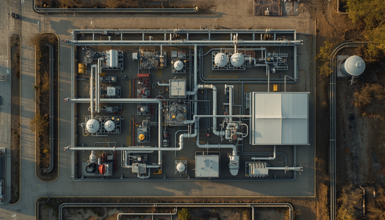
Plant layout is one of the most consequential decisions in industrial plant design. It affects construction cost, operating efficiency, maintenance access, safety, and future expansion. For small-scale industrial plants, layout decisions are especially critical because there is less space to work with and less margin for error.
This article covers the key considerations that drive effective layout design for small to medium-scale industrial plants. Whether you are planning a biomass facility, a small thermal plant, or a process plant, these principles apply.
Plot Plan vs. Equipment Layout
Two related but distinct documents define a plant’s layout:
- Plot plan: The site-level arrangement of buildings, roads, major equipment, tanks, utilities, and boundaries.
- Equipment layout: The detailed arrangement of equipment, piping, and access within a building, structure, or process area.
For small plants, the plot plan often determines whether the project is feasible at all. Site boundaries, setbacks, access roads, and separation distances are fixed early, and they constrain everything that follows. This article addresses both levels, but the plot plan should be settled before detailed equipment layout begins.
Why Layout Matters More for Small Plants
Large plants often have enough space to accommodate imperfect layouts. Small plants do not. Every meter counts. A poorly planned layout in a small plant can lead to:
- Higher construction cost: Extra piping, longer cable runs, and additional structural steel.
- Inefficient operations: Longer travel distances for operators and maintenance staff.
- Safety risks: Inadequate separation between hazardous areas.
- Limited expansion: No room to add equipment or capacity later.
- Maintenance difficulties: Equipment that cannot be accessed for service.
For these reasons, layout should be treated as a strategic decision, not a drafting exercise.
The Core Objectives of Plant Layout
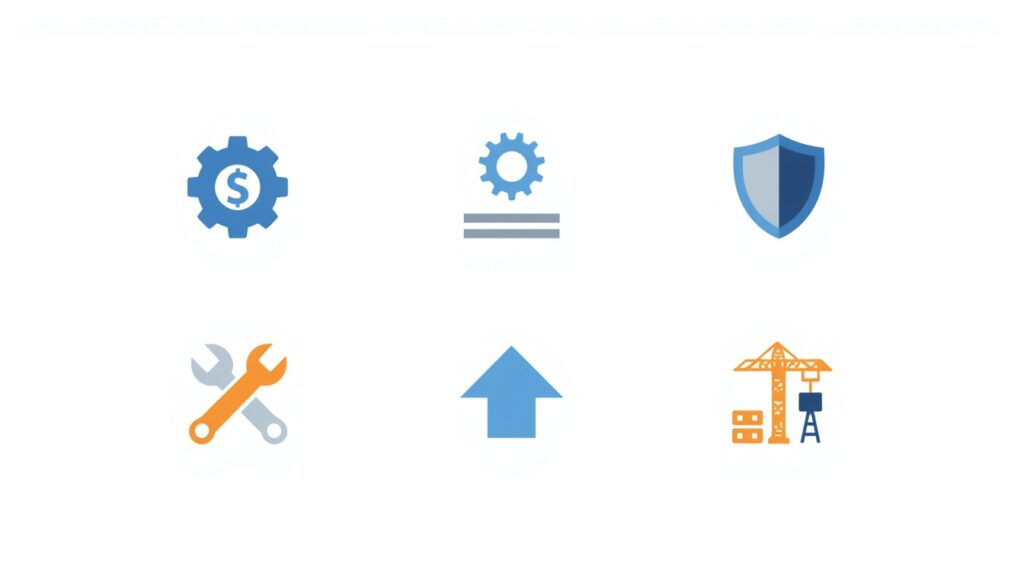
A good layout achieves several objectives simultaneously:
| Objective | What It Means |
|---|---|
| Minimize capital cost | Reduce piping, cabling, and structural requirements |
| Optimize operations | Place equipment in logical process order |
| Ensure safety | Separate hazardous areas and provide clear escape routes |
| Enable maintenance | Provide access for inspection, repair, and replacement |
| Allow expansion | Reserve space for future equipment or capacity increase |
| Facilitate construction | Allow efficient sequencing of civil, mechanical, and electrical work |
These objectives sometimes conflict. For example, minimizing cost may push equipment closer together, but safety and maintenance requirements may demand more space. Good layout design balances these trade-offs.
Key Considerations
1. Process Flow
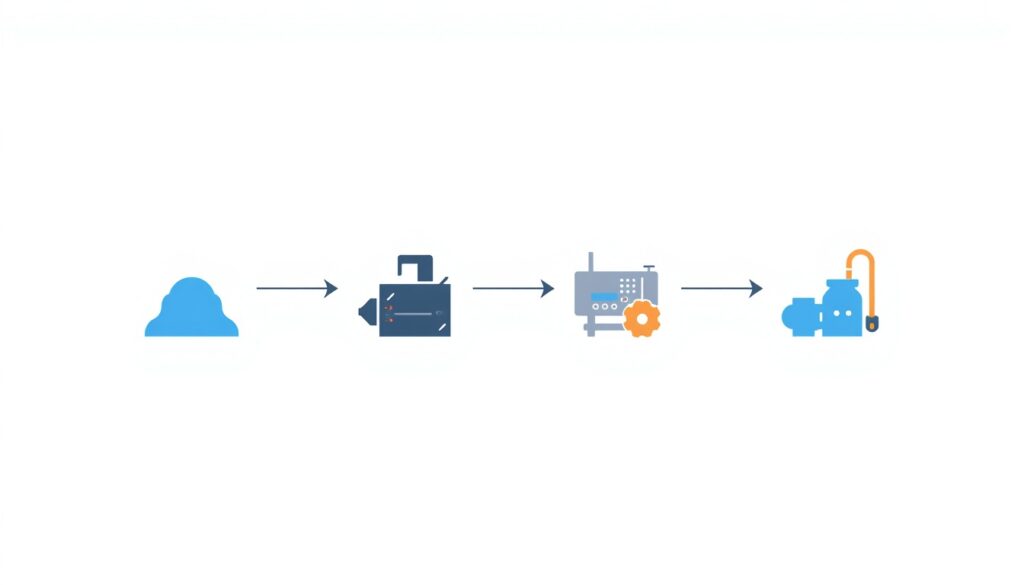
The layout should follow the process flow as closely as possible. Raw material should enter at one end, and finished product or output should exit at the other. This minimizes piping runs, reduces pressure drops, and simplifies operation.
For small plants, a linear or L-shaped layout often works best. Linear layouts minimize piping runs and simplify construction, while L-shaped layouts allow the plant to fit into constrained sites while preserving process flow. Both are simple, efficient, and easy to expand.
2. Equipment Spacing
Equipment must be spaced to allow:
- Operation: Space for operators to monitor and adjust equipment.
- Maintenance: Room to remove and replace components such as heat exchangers, pumps, and motors.
- Safety: Adequate distance between hot surfaces, electrical equipment, and flammable materials.
- Ventilation: Airflow to prevent heat buildup and gas accumulation.
Manufacturers typically provide minimum clearance recommendations. These should be treated as minimums, not targets.
3. Piping, Pipe Racks, and Cable Routing
Piping and cabling are significant cost drivers. A layout that minimizes the length and complexity of these runs reduces both capital cost and pressure losses.
Key principles:
- Group equipment that shares piping or cabling connections.
- Use common pipe racks and cable trays where possible.
- Avoid unnecessary elevation changes in piping.
- Route cables away from hot or hazardous areas.
Pipe racks as the backbone of the layout. In many plants, the pipe rack is the organizing element around which everything else is arranged. Its location drives equipment spacing, since equipment is typically placed along both sides of the rack. It also drives construction sequence, because rack foundations and steel are often erected early so that piping and cable trays can be installed as equipment arrives. Deciding rack location and routing early, ideally alongside the plot plan, avoids expensive rework later. Leave spare capacity on the rack for future lines, and keep power and instrument cable trays segregated from process piping according to applicable standards.
4. Access and Egress
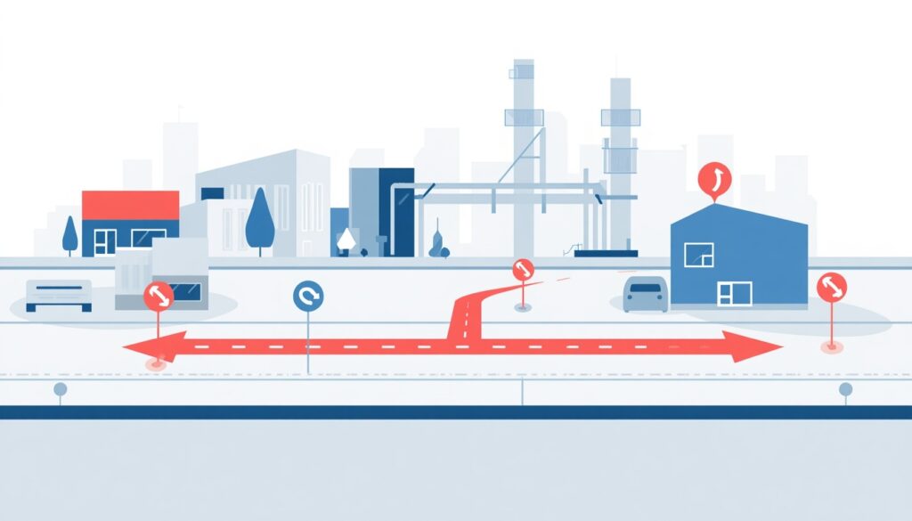
Safe access is essential. The layout must provide:
- Primary access routes: For normal operations and maintenance.
- Emergency egress routes: For evacuation during an incident.
- Vehicle access: For deliveries, mobile equipment, and emergency response.
- Pedestrian access: Separate from vehicle routes where possible.
In small plants, access routes often do double duty. This requires careful planning to avoid conflicts.
5. Safety, Hazard Separation, and Regulatory Compliance
Safety should be a primary driver of layout, not an afterthought. Key considerations include:
- Separation distances: Between hazardous and non-hazardous areas.
- Fire zones: Segregation of equipment by fire risk.
- Explosion protection: Location of electrical equipment relative to flammable areas.
- Toxic gas dispersion: Placement of vents and stacks relative to occupied areas.
- Emergency shutdown: Access to isolation valves and controls.
Recognized codes and standards (such as NFPA, IEC, and API) provide guidance on separation distances. These must be respected.
Regulatory compliance. Local regulations often dictate separation distances, fire zone requirements, and emergency access routes. These must be identified early, as they can constrain the layout significantly. A layout that is efficient on paper but fails a permit review can force a costly redesign.
6. Maintenance and Replacement
Equipment must be accessible for maintenance. The layout should allow:
- Removal of major components: Heat exchanger tubes, turbine rotors, and pump internals.
- Lifting access: Overhead clearance for cranes or mobile lifting equipment.
- Workspace: Room for maintenance personnel and tools.
- Spare parts storage: Nearby but not blocking access.
For small plants, maintenance access is often compromised by tight layout. This should be addressed early in design, not discovered during operation.
Operation vs. maintenance. Layout for operation and layout for maintenance sometimes conflict. A compact layout may be efficient for operations but difficult for maintenance. The trade-off should be evaluated explicitly.
7. Future Expansion
Even small plants sometimes need to expand. A good layout reserves space for:
- Additional equipment: Parallel process lines, additional pumps, or extra capacity.
- Utility upgrades: Larger transformers, additional cooling capacity.
- Control system expansion: Space for additional panels or instruments.
- Site infrastructure: Roads, parking, and storage.
Expansion space should be identified during initial design, even if expansion is not certain.
8. Construction Sequence
Layout affects how the plant is built. A layout that allows efficient construction sequencing can reduce schedule and cost. Key considerations include:
- Access for construction equipment: Cranes, trucks, and heavy lift equipment.
- Laydown areas: Space for temporary storage of materials and equipment.
- Sequencing: Ability to install equipment in a logical order without blocking access.
- Temporary facilities: Site offices, warehouses, and worker facilities.
For small plants, construction access is often constrained. Early planning helps avoid delays.
9. 3D Modeling and Clash Detection
Modern layout design uses 3D modeling to detect clashes between piping, structural, and electrical systems before construction begins. This reduces field changes and rework. In tight small-plant layouts, where piping, steel, cable trays, and maintenance envelopes compete for the same space, clash detection is especially valuable. The 3D model can also be used to check maintenance access and lifting paths, not just physical interferences.
Common Layout Mistakes
Even experienced designers make mistakes. Common ones include:
- Insufficient maintenance access: Equipment installed too close to walls or other equipment.
- Ignoring expansion: No space reserved for future needs.
- Poor process flow: Equipment arranged inefficiently, increasing piping and operating cost.
- Inadequate safety separation: Hazardous areas too close to occupied areas.
- Overlooking construction access: Equipment that cannot be delivered or installed.
- Forgetting utilities: Insufficient space for piping, cabling, and instrumentation.
These mistakes are costly to fix after construction begins. They are much cheaper to avoid during design.
How Japanese EPC Firms Approach Layout
Japanese engineering firms often take a disciplined approach to plant layout. Common characteristics include:
- Thorough front-end planning: Layout is developed early and refined through multiple reviews.
- Attention to detail: Clearances, access routes, and maintenance space are carefully considered.
- Safety focus: Hazard separation and emergency access are prioritized.
- Long-term perspective: Expansion space is reserved even when not immediately needed.
- Constructability review: Layout is evaluated for ease of construction, not just operation.
For plant owners, this often means a layout that is efficient, safe, and adaptable to future needs.
How to Evaluate a Layout
When reviewing a proposed layout, ask:
| Question | Why It Matters |
|---|---|
| Does it follow the process flow? | Minimizes piping and operating cost |
| Is there adequate maintenance access? | Reduces downtime and maintenance cost |
| Are safety separations respected? | Protects people and assets |
| Is there space for expansion? | Avoids costly future modifications |
| Can it be constructed efficiently? | Reduces schedule and cost |
| Are utilities properly routed? | Avoids conflicts and inefficiencies |
| Is it compliant with regulations? | Ensures legal and safe operation |
A layout that satisfies all these questions is likely to perform well over the plant’s life.
Conclusion
Plant layout is not just a drawing exercise. It is a strategic decision that affects cost, safety, operations, and future flexibility. For small-scale industrial plants, where space is limited and margins are tight, layout deserves careful attention from the earliest stages of design.
By focusing on process flow, equipment spacing, safety, maintenance access, and expansion, owners and designers can create layouts that are efficient, safe, and built to last.
Key Takeaways
- Plant layout affects cost, safety, operations, and future flexibility.
- The plot plan often determines project feasibility, so settle it before detailed equipment layout.
- Process flow should drive the overall arrangement.
- Equipment spacing must allow operation, maintenance, and safety.
- Access and egress must be planned for normal and emergency conditions.
- Local regulations should be identified early, since they can constrain the layout significantly.
- 3D modeling and clash detection reduce field changes and rework.
- Japanese EPC firms emphasize front-end planning and constructability review.