Tag: Plant Design

  • Combined Cycle vs. Simple Cycle: Choosing the Right Configuration for Your Plant

    Combined Cycle vs. Simple Cycle: Choosing the Right Configuration for Your Plant

    When planning a thermal power plant, one of the first configuration decisions is whether to use a simple cycle or a combined cycle. This choice affects capital cost, efficiency, fuel consumption, emissions, and operational flexibility. For small to medium-scale industrial plants, the right choice depends on your load profile, fuel availability, site constraints, and financial objectives.

    This article explains the difference between simple cycle and combined cycle, compares them side by side, and helps you decide which configuration fits your project.

    Note on fuel: this article assumes natural gas throughout. Gas turbines can also run on liquid fuels such as distillate and on syngas. Simple cycle plants are generally more fuel-flexible, while combined cycle plants are most often gas-fired, with liquid fuel typically used only as backup.

    What Is a Simple Cycle Plant?

    A simple cycle plant uses a gas turbine to generate electricity directly. The turbine burns fuel, produces hot exhaust gas, and drives a generator. The exhaust gas is then released to the atmosphere.

    Simple cycle plants are:

    • Simple to design and build: Fewer components, shorter construction time.
    • Lower in capital cost: Less equipment, smaller footprint.
    • Fast to start: Can reach full load in minutes.
    • Less efficient: Typical efficiency of 30–40%.
    • Higher heat rate: More fuel consumed per unit of output.

    Simple cycle plants are often used for peaking power, backup generation, and remote locations where simplicity and speed matter more than efficiency.

    What Is a Combined Cycle Plant?

    A combined cycle plant uses both a gas turbine and a steam turbine to generate electricity. The gas turbine produces electricity, and its hot exhaust gas is directed to a heat recovery steam generator (HRSG). The HRSG produces steam, which drives a steam turbine to generate additional electricity.

    Combined cycle plants are:

    • More efficient: Typical efficiency of 50–60% or higher.
    • Lower heat rate: Less fuel consumed per unit of output.
    • Higher capital cost: More equipment, larger footprint.
    • Slower to start: Takes longer to reach full load.
    • More complex to design and operate.

    Combined cycle plants are often used for baseload power, where high efficiency and low fuel cost are priorities.

    The Key Difference
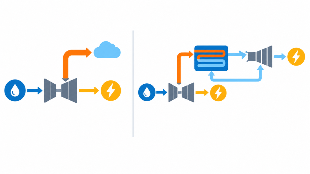
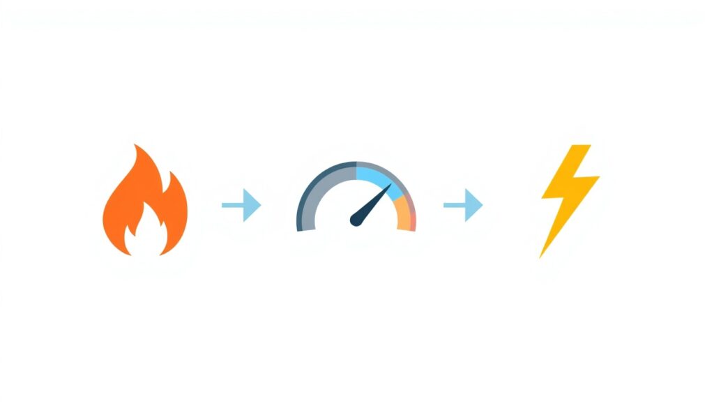
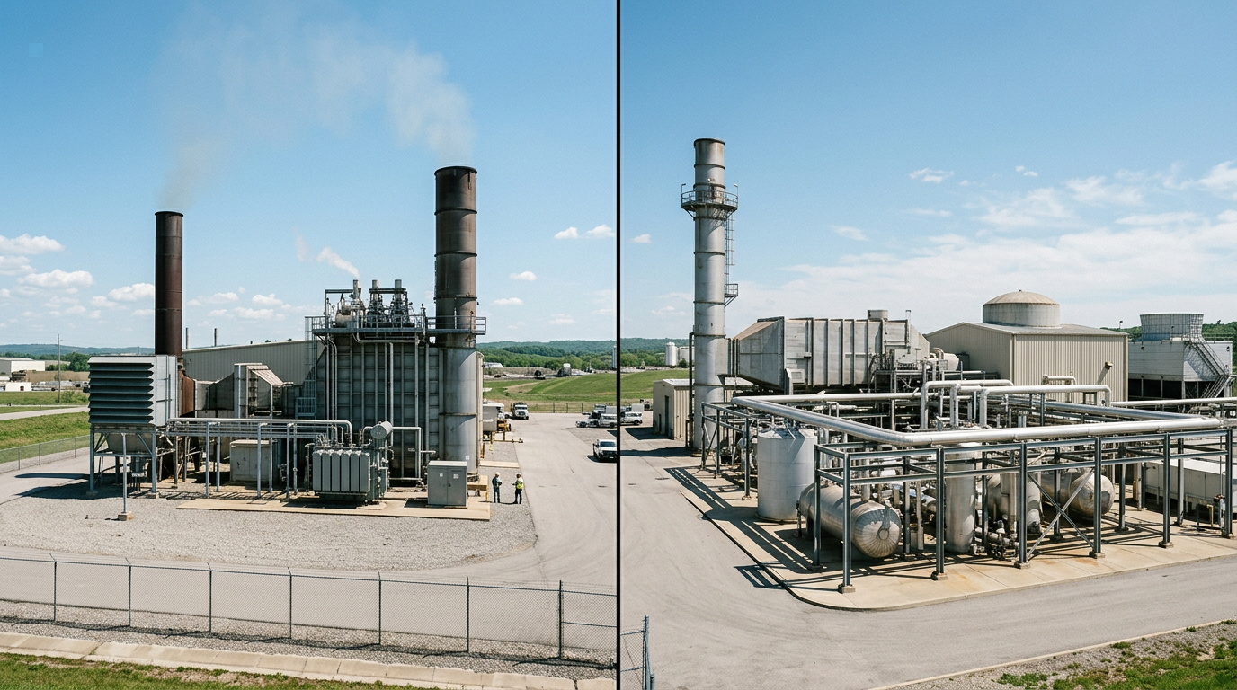
    Simple cycle versus combined cycle energy flow diagram

    The fundamental difference is waste heat recovery.

    In a simple cycle plant, the hot exhaust gas from the gas turbine is wasted. In a combined cycle plant, that heat is captured and used to generate additional electricity.

    This is why combined cycle plants achieve much higher efficiency. By recovering waste heat, they extract more useful energy from the same fuel.

    Side-by-Side Comparison

    Factor Simple Cycle Combined Cycle
    Efficiency 30–40% 50–60% or higher
    Heat rate Higher (more fuel per kWh) Lower (less fuel per kWh)
    Capital cost Lower Higher
    Footprint Smaller Larger
    Construction time Shorter Longer
    Startup time Fast (minutes) Slower (30–60 minutes hot start; several hours cold)
    Operational flexibility High Lower
    Emissions per kWh Higher Lower
    Typical use Peaking, backup Baseload, industrial
    Sensitivity to fuel price High Lower

    When Simple Cycle Makes Sense

    Simple cycle is often the right choice when:

    • Capital cost is the primary constraint. If budget is limited, simple cycle requires less upfront investment.
    • The plant operates infrequently. Peaking plants that run only a few hundred hours per year do not benefit much from higher efficiency.
    • Fast startup is critical. Simple cycle plants can reach full load in minutes, making them ideal for grid support.
    • The site is remote or constrained. Smaller footprint and simpler infrastructure reduce site requirements.
    • Fuel is cheap or subsidized. If fuel cost is low, the efficiency penalty of simple cycle matters less.
    • The project needs to be built quickly. Shorter construction time can be a decisive advantage.

    When Combined Cycle Makes Sense

    Combined cycle is often the right choice when:

    • The plant operates frequently. Baseload or industrial plants that run thousands of hours per year benefit greatly from higher efficiency.
    • Fuel cost is significant. Lower heat rate translates directly into lower operating cost.
    • Emissions limits are tight. Combined cycle produces less CO₂ and other emissions per kWh.
    • Long-term economics matter more than upfront cost. Higher capital cost is recovered through fuel savings over the plant’s life.
    • The site can accommodate a larger plant. Combined cycle requires more space for the HRSG, steam turbine, and cooling systems.
    • The load profile is stable. Combined cycle plants perform best when operating at steady, high load.

    The Economics of Combined Cycle
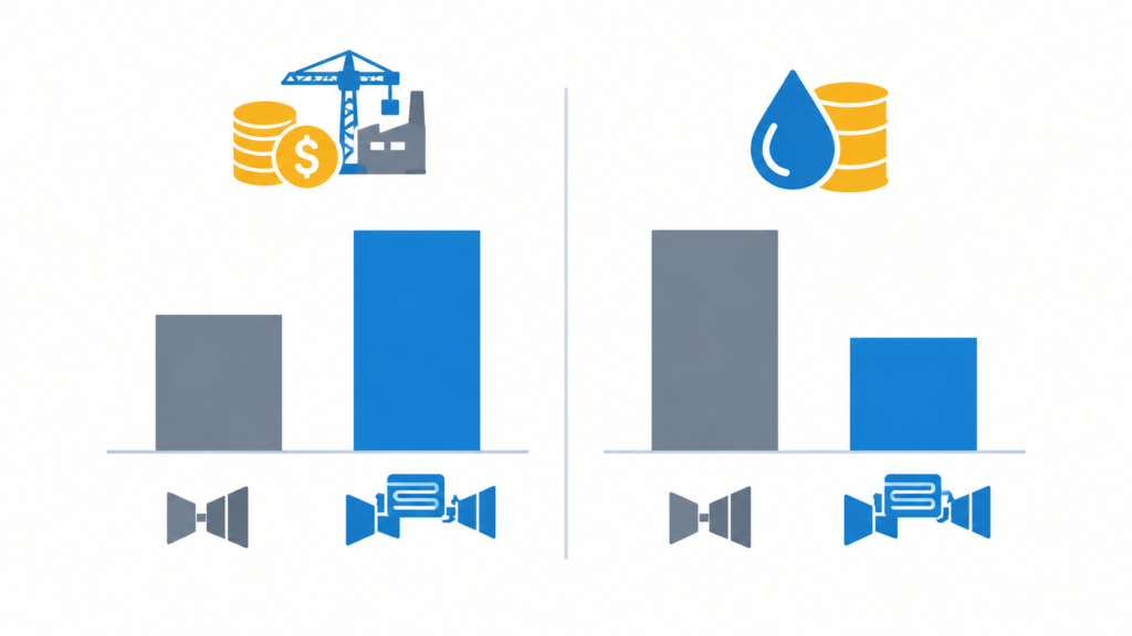
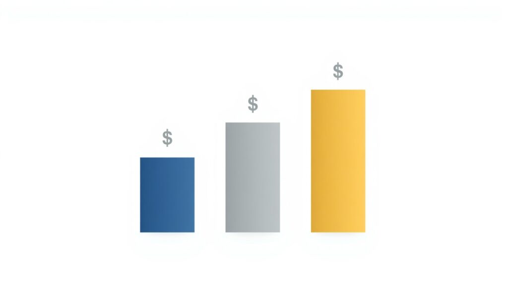
    Economics comparison of combined cycle and simple cycle power plants

    The higher capital cost of combined cycle is justified by fuel savings over the plant’s life. The payback period depends on:

    • Fuel cost: Higher fuel cost favors combined cycle.
    • Operating hours: More hours per year favor combined cycle.
    • Load factor: Higher average load favors combined cycle.
    • Capital cost premium: A smaller gap between the two options shortens the payback. (If you evaluate NPV rather than simple payback, a lower discount rate also favors long-term savings.)

    A simplified, illustrative comparison for a 50 MW plant operating 8,000 hours per year at a fuel price of about $7.3/MMBtu:

    Parameter Simple Cycle Combined Cycle
    Capital cost $50 million $75 million
    Efficiency 35% 55%
    Fuel cost per year (at 8,000 hours) $28.6 million $18.2 million
    Annual fuel savings — $10.4 million
    Simple payback — ~2.4 years

    In this example, the additional $25 million capital cost is recovered in about 2.4 years through fuel savings. After that, the combined cycle plant saves over $10 million per year, before accounting for its higher maintenance costs.

    Note that 8,000 hours per year is close to baseload operation. At 2,000 hours per year, annual fuel savings fall to roughly $2.6 million and the payback stretches to roughly 10 years, which makes simple cycle considerably more attractive. This simple payback also excludes O&M and financing costs, which would lengthen both figures.

    Operational Considerations

    Beyond economics, simple cycle and combined cycle differ in operational characteristics.

    Startup and shutdown:

    • Simple cycle: Fast start, suitable for peaking and grid support.
    • Combined cycle: Slower start, less suitable for rapid load changes.

    Part-load efficiency:

    • Simple cycle: Efficiency drops significantly at part load.
    • Combined cycle: Efficiency also drops at part load, but less steeply.

    Maintenance:

    • Simple cycle: Fewer components, simpler maintenance.
    • Combined cycle: More components, including HRSG and steam turbine, requiring more maintenance.

    Reliability:

    • Simple cycle: Fewer systems, potentially higher reliability.
    • Combined cycle: More systems, but redundancy can be built in.

    For small plants, operational simplicity may be more valuable than maximum efficiency. This is a key trade-off to consider.

    Environmental Considerations

    Combined cycle plants produce less CO₂ per kWh because they consume less fuel. NOx emissions per kWh are also lower, mainly because higher efficiency means less exhaust per unit of output, although both configurations need appropriate combustion controls or exhaust treatment to meet permit limits. Combined cycle is also generally better suited to future post-combustion carbon capture, since the HRSG and steam system can supply the heat needed for solvent regeneration and higher operating hours better justify the investment.

    For plants subject to strict emissions regulations or carbon pricing, combined cycle is often the more practical option. For plants in regions with lax emissions rules and cheap fuel, simple cycle may be acceptable.

    How Japanese EPC Firms Approach This

    Japanese engineering firms often favor combined cycle for industrial plants where efficiency and long-term operating cost matter. Common characteristics include:

    • Life-cycle cost focus: Combined cycle is evaluated on total cost, not just capital cost.
    • Conservative design: Adequate margins for fuel variation and ambient conditions.
    • Detailed performance testing: Heat rate and output guarantees are carefully verified.
    • Long-term support: Ongoing monitoring and optimization after commissioning.
    • Emissions compliance: Designs that meet or exceed environmental standards.

    For plant owners, this often means a configuration that delivers low operating cost and reliable performance over decades.

    How to Decide

    Ask yourself these questions:

    Question If Yes If No
    Will the plant operate more than 4,000 hours per year? (rule of thumb; depends on fuel price) Combined cycle Simple cycle
    Is fuel cost a major concern? Combined cycle Simple cycle
    Is capital cost the primary constraint? Simple cycle Combined cycle
    Is fast startup critical? Simple cycle Combined cycle
    Are emissions limits tight? Combined cycle Simple cycle
    Is the site large enough for combined cycle? Combined cycle Simple cycle
    Is long-term economics more important than upfront cost? Combined cycle Simple cycle

    For most small to medium-scale industrial plants that operate frequently, combined cycle is the better choice. For peaking plants or sites with tight constraints, simple cycle may be more appropriate.

    Conclusion

    Simple cycle and combined cycle are both valid configurations for thermal power plants. Simple cycle offers lower capital cost, faster startup, and simpler operation. Combined cycle offers higher efficiency, lower fuel cost, and lower emissions.

    The right choice depends on your load profile, fuel cost, site constraints, and financial objectives. By evaluating these factors carefully, you can select the configuration that delivers the best long-term value for your plant.

    Key Takeaways

    • Simple cycle: lower capital cost, faster start, lower efficiency.
    • Combined cycle: higher capital cost, higher efficiency, lower fuel cost per kWh.
    • Choose combined cycle for frequent operation and high fuel cost.
    • Choose simple cycle for peaking duty, remote sites, or tight budgets.

  • Understanding Heat Rate and Thermal Efficiency in Industrial Plants

    Understanding Heat Rate and Thermal Efficiency in Industrial Plants

    Heat rate is one of the most important performance metrics in thermal power generation. It measures how efficiently a plant converts fuel into electricity. For plant owners, heat rate directly affects operating cost, fuel consumption, and profitability.

    Despite its importance, heat rate is often misunderstood. It is sometimes confused with thermal efficiency, and its relationship to fuel cost is not always clear. This article explains what heat rate is, how it is calculated, what affects it, and why it matters for small to medium-scale industrial plants.

    What Is Heat Rate?

    Heat rate energy input and output illustration

    Heat rate is the amount of energy input required to produce one unit of energy output. In power generation, it is typically expressed in kJ/kWh (kilojoules per kilowatt-hour) or Btu/kWh (British thermal units per kilowatt-hour). To convert between them, 1 kJ/kWh ≈ 0.948 Btu/kWh (equivalently, 1 Btu/kWh ≈ 1.055 kJ/kWh). This article uses kJ/kWh throughout.

    A lower heat rate means better efficiency. A higher heat rate means more fuel is required to produce the same output.

    For example:

    • A plant with a heat rate of 10,000 kJ/kWh requires 10,000 kJ of fuel energy to produce 1 kWh of electricity.
    • A plant with a heat rate of 8,000 kJ/kWh requires only 8,000 kJ of fuel energy to produce the same 1 kWh.

    The second plant is more efficient and will have lower fuel costs for the same output.

    One caution on the fuel side: heat rate can be based on the fuel’s lower heating value (LHV) or higher heating value (HHV). HHV-based figures are higher (worse) than LHV-based figures for the same plant, by roughly 10% for natural gas and less for coal. Always confirm which basis is being used before comparing numbers.

    Heat Rate vs. Thermal Efficiency

    Heat rate and thermal efficiency are related but not identical. Thermal efficiency is the ratio of useful output to energy input, expressed as a percentage.

    The relationship is:

    Thermal Efficiency (%) = 3,600 / Heat Rate (kJ/kWh) × 100 (3,600 kJ = 1 kWh)

    The 3,600 is simply the number of kilojoules in one kilowatt-hour, that is, the energy content of one unit of electrical output. In Btu units, the equivalent constant is 3,412 Btu = 1 kWh.

    For example:

    • Heat rate of 10,000 kJ/kWh → efficiency = 36%
    • Heat rate of 8,000 kJ/kWh → efficiency = 45%
    • Heat rate of 12,000 kJ/kWh → efficiency = 30%

    In simple terms:

    • Lower heat rate = higher efficiency
    • Higher heat rate = lower efficiency

    Both metrics describe the same thing from different angles. Heat rate is preferred in some regions and industries; thermal efficiency is preferred in others.

    Why Heat Rate Matters

    Heat rate matters because fuel is the largest operating cost for most thermal plants. A small improvement in heat rate can translate into significant savings over the plant’s life.

    Consider a plant that consumes fuel at a cost of $5 per million kJ (equivalent to $5/GJ, or roughly $5.3/MMBtu). Fuel prices vary widely by region and over time, so the absolute numbers below are illustrative; substitute your own fuel contract price.

    Heat Rate (kJ/kWh) Fuel Cost per kWh Annual Fuel Cost (100 MW plant, full load, 8,760 h/year)
    12,000 $0.060 $52.6 million
    10,000 $0.050 $43.8 million
    8,000 $0.040 $35.0 million

    The difference between a heat rate of 12,000 and 8,000 is about $17.5 million per year for a 100 MW plant running continuously at full output. For smaller plants, the absolute numbers are lower, but the percentage impact is the same.

    This is why heat rate is often a key performance guarantee in EPC contracts. If the plant does not meet its guaranteed heat rate, the contractor may be liable for liquidated damages.

    For context, guarantee values depend on plant type, size, and the basis used (LHV or HHV, gross or net). For combined cycle plants, guarantees typically range from 6,000 to 7,500 kJ/kWh. For simple cycle plants, 9,000 to 12,000 kJ/kWh is common. Smaller plants tend toward the upper end of these ranges or above them.

    What Affects Heat Rate?

    Many factors influence a plant’s heat rate. Some are design-related, others are operational.

    Design factors:

    • Cycle configuration: Combined cycle plants have lower heat rates than simple cycle plants.
    • Equipment efficiency: Turbine, boiler, and generator efficiency all affect heat rate.
    • Steam conditions: Higher temperature and pressure improve efficiency.
    • Condenser performance: Better vacuum improves efficiency.
    • Auxiliary power consumption: Pumps, fans, and controls consume power, increasing net heat rate.

    Operational factors:

    • Load level: Plants are usually most efficient at or near full load.
    • Ambient conditions: Higher ambient temperature reduces output and increases heat rate.
    • Fuel quality: Lower heating value or impurities can reduce efficiency.
    • Equipment degradation: Fouling, wear, and leaks increase heat rate over time.
    • Operational practices: Startup, shutdown, and part-load operation affect average heat rate.

    For small plants, operational factors often have a larger impact because there is less design margin.

    Gross vs. Net Heat Rate

    Heat rate can be expressed as gross or net.

    • Gross heat rate: Based on total generator output, before subtracting auxiliary power consumption.
    • Net heat rate: Based on net output delivered to the grid, after subtracting auxiliary power.

    Net heat rate is always higher (worse) than gross heat rate because auxiliary equipment consumes power. For plant owners, net heat rate is the more relevant metric because it reflects the actual output available for sale.

    A common mistake is to compare gross heat rates from different plants without adjusting for auxiliary power. Always confirm which basis is being used.

    How Heat Rate Is Measured

    Heat rate is determined through performance testing, typically conducted after commissioning. The test measures:

    • Fuel input: Flow rate and heating value of fuel
    • Power output: Gross and net electrical output
    • Auxiliary power: Consumption of pumps, fans, and other equipment
    • Ambient conditions: Temperature, pressure, and humidity

    International standards such as ASME PTC 46 (overall plant performance) or ISO 2314 (gas turbines) provide procedures for conducting and reporting these tests. The results are used to verify contractual performance guarantees.

    Improving Heat Rate

    Heat rate can be improved through both design and operational measures.

    Design improvements:

    • Higher steam conditions: Supercritical or ultra-supercritical cycles (mainly practical for large utility-scale plants)
    • Combined cycle: Recovering waste heat from exhaust gases
    • Better condensers: Lower condenser pressure improves efficiency
    • Efficient auxiliaries: Variable frequency drives, high-efficiency motors
    • Advanced controls: Optimizing combustion and load allocation

    Operational improvements:

    • Operating at design point: Running at or near full load
    • Regular maintenance: Cleaning heat exchangers, repairing leaks, replacing worn components
    • Fuel management: Using consistent, high-quality fuel
    • Performance monitoring: Tracking heat rate trends to detect degradation
    • Operator training: Ensuring best practices for startup, shutdown, and load changes

    For existing plants, operational improvements often provide the fastest payback. For new plants, design improvements are built in from the start.

    Common Mistakes in Heat Rate Management

    Even experienced operators make mistakes. Common ones include:

    • Ignoring auxiliary power: Focusing on gross heat rate instead of net
    • Comparing at different conditions: Not correcting for ambient temperature or fuel quality
    • Neglecting degradation: Assuming heat rate stays constant over time
    • Operating at part load: Running at low load when full load is possible
    • Skipping performance tests: Not verifying heat rate after major overhauls
    • Poor fuel quality: Using inconsistent or low-quality fuel that increases heat rate

    These mistakes can lead to higher operating costs and missed performance targets.

    How Japanese EPC Firms Approach Heat Rate

    Japanese engineering firms are known for their focus on thermal efficiency. Common characteristics include:

    • Conservative design margins: Equipment is specified with enough margin to maintain performance over time.
    • Detailed performance testing: Heat rate tests are carefully planned and executed.
    • Long-term monitoring: Performance is tracked over the plant’s life, not just at commissioning.
    • Operational support: Japanese firms often provide ongoing support to help owners maintain efficiency.
    • Continuous improvement: Lessons from each project are applied to the next.

    For plant owners, this often means a plant that meets its heat rate guarantee and maintains performance over time.

    How to Evaluate Heat Rate Performance

    When reviewing heat rate performance, ask:

    Question Why It Matters
    Is the heat rate gross or net? Net heat rate reflects actual output for sale
    Is it based on LHV or HHV? The two bases differ by roughly 5–10%, depending on fuel
    What conditions apply? Heat rate varies with ambient temperature and fuel
    Has it been corrected to reference conditions? Allows comparison across different tests
    How has it changed over time? Detects degradation and maintenance needs
    How does it compare to the guarantee? Determines whether the contractor has met obligations
    What is the fuel cost impact? Translates heat rate into financial terms

    A plant that understands its heat rate performance can manage fuel costs, plan maintenance, and verify contractual compliance.

    Conclusion

    Heat rate is a fundamental measure of thermal plant efficiency. It directly affects fuel cost, operating profitability, and contractual performance. For small to medium-scale industrial plants, where margins are tight, understanding and managing heat rate is essential.

    By focusing on design efficiency, operational practices, and continuous monitoring, owners and operators can keep heat rate low and fuel costs under control.

    Key Takeaways

    • Heat rate measures fuel energy input per unit of electricity output.
    • Lower heat rate = higher efficiency.
    • Net heat rate reflects actual output for sale.
    • Heat rate is affected by design, operation, and ambient conditions.
    • Regular monitoring detects degradation and supports maintenance planning.
  • Equipment Selection Criteria for Small to Medium-Scale Industrial Plants

    Equipment Selection Criteria for Small to Medium-Scale Industrial Plants

    Equipment selection is one of the most consequential decisions in plant design. The equipment you choose determines capital cost, operating cost, reliability, maintenance requirements, and ultimately whether the plant meets its performance targets.

    For small to medium-scale industrial plants, equipment selection is especially critical. There is less redundancy, less margin for error, and less room to absorb the consequences of a poor choice. A pump that is oversized wastes energy for decades. A heat exchanger that is undersized limits output from day one.

    This article covers the key criteria that drive effective equipment selection for small to medium-scale plants. Whether you are specifying a boiler, a turbine, a pump, or a control system, these principles apply.

    Why Equipment Selection Matters More for Small Plants

    Large plants often have redundancy built into their designs. If one pump fails, a backup takes over. If one heat exchanger fouls, another compensates. Small plants rarely have this luxury.

    The consequences of poor equipment selection in a small plant include:

    • Higher capital cost: Oversized or over-specified equipment increases upfront investment.
    • Higher operating cost: Inefficient equipment consumes more fuel, power, or chemicals over its life.
    • Reduced reliability: Equipment that is marginal for the application fails more often.
    • Maintenance burden: Equipment that is difficult to service increases downtime and cost.
    • Limited flexibility: Equipment that cannot handle variations in load or feedstock restricts operations.

    For these reasons, equipment selection should be treated as a strategic decision, not a procurement formality.

    The Core Criteria for Equipment Selection

    Core criteria for industrial plant equipment selection

    A good equipment selection process evaluates each item against several criteria simultaneously:

    Criterion What It Means
    Technical suitability Does the equipment meet process requirements?
    Reliability How often does it fail, and how severe are failures?
    Efficiency How much energy, fuel, or consumable does it use?
    Capital cost What is the purchase price, including installation?
    Operating cost What are the ongoing costs of energy, maintenance, and spares?
    Maintainability How easy is it to inspect, repair, and replace?
    Lead time How long until delivery, and does it fit the schedule?
    Vendor support Does the supplier provide spares, service, and technical support?
    Compliance Does it meet codes, standards, and environmental requirements?

    These criteria sometimes conflict. A highly efficient piece of equipment may cost more upfront. A reliable vendor may have a longer lead time. Good selection balances these trade-offs.

    Technical Suitability

    The first question is always: does the equipment meet the process requirements?

    This includes:

    • Capacity: Can it handle the required flow, pressure, temperature, or load?
    • Range: Can it operate across the expected range of conditions?
    • Turndown: Can it operate stably and efficiently down to the minimum expected load?
    • Compatibility: Is it compatible with the process fluid, fuel, or environment?
    • Interfaces: Does it connect properly with upstream and downstream equipment?

    Manufacturers provide performance curves and datasheets that define these limits. These should be reviewed carefully, not assumed.

    A common mistake is selecting equipment that meets design conditions but performs poorly at off-design conditions. For small plants, which often operate across a wide range of loads, turndown and part-load efficiency are especially important.

    Equipment selection also directly affects whether the plant can meet its performance guarantees. If the plant must achieve a guaranteed heat rate or output, every major item must be capable of supporting it. A pump or heat exchanger that is marginal at design conditions may cause the entire plant to fall short. (See [title/link of article on performance guarantees].)

    Standardization vs. Customization

    For small plants, standard, off-the-shelf equipment is usually preferable to custom-designed units. Catalogue equipment typically costs less, is delivered faster, has a proven field record, and uses spare parts that are easier to source and interchange. Standardizing on the same models across the plant, such as a single pump family, also reduces the number of different spares to hold and simplifies operator training.

    Customization is justified when standard equipment cannot meet a process requirement or offers a clear performance advantage. Even then, its added cost, longer lead time, and heavier spares burden should be weighed explicitly rather than accepted by default.

    Reliability

    Reliability is the probability that equipment will perform its function without failure over a given period. For small plants, reliability is critical because there is often no redundancy.

    Key reliability considerations include:

    • Mean time between failures (MTBF): How often does the equipment fail?
    • Mean time to repair (MTTR): How long does it take to restore operation after a failure?
    • Failure mode: Does failure result in a safe shutdown or a hazardous condition?
    • Service history: How has this equipment performed in similar applications?

    Reliability data can come from manufacturer records, industry databases, or references from other plant owners. Do not rely solely on vendor claims.

    For critical equipment, consider whether redundancy is justified. A single spare pump may cost less than the production lost during a failure.

    Efficiency

    Efficiency determines how much energy or fuel the equipment consumes over its life. For equipment that runs continuously, efficiency often matters more than capital cost.

    Consider a pump, for example. Suppose it draws 100 kW and runs 8,000 hours per year at an electricity price of $0.10/kWh. Its annual energy cost is about $80,000. A pump that draws 5% less power saves about $4,000 per year, or roughly $40,000 over 10 years. If the more efficient pump carries a 20% price premium on a typical $20,000 unit, that premium is only $4,000, so it pays for itself in about one year. Even after discounting future savings (about $27,000 at an 8% discount rate), the energy savings far exceed the price difference.

    The same logic applies to boilers, turbines, compressors, and heat exchangers. The key is to evaluate life-cycle cost, not just purchase price.

    Capital Cost vs. Operating Cost

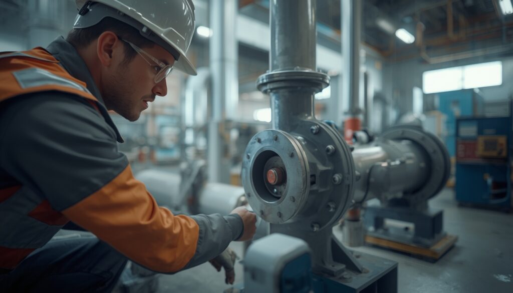
    Capital cost versus operating cost trade-off in equipment selection

    Equipment selection often involves a trade-off between capital cost and operating cost. A cheaper piece of equipment may consume more energy, require more maintenance, or fail more often.

    The tool for evaluating this trade-off is life-cycle cost analysis, also known as total cost of ownership (TCO) analysis. This sums:

    • Purchase price
    • Installation cost
    • Energy cost over the equipment’s life
    • Maintenance and spares cost
    • Downtime cost
    • Disposal or replacement cost

    For small plants, where margins are tight, life-cycle cost (TCO) is often the most important criterion. A slightly higher upfront investment in efficient, reliable equipment usually pays back many times over.

    Maintainability

    Maintainability considerations in industrial plant equipment selection

    Equipment must be maintainable. This means:

    • Access: Can it be reached for inspection and repair?
    • Disassembly: Can components be removed and replaced without major work?
    • Standardization: Are parts standard, or are they proprietary and slow to source?
    • Documentation: Are manuals, drawings, and procedures available?
    • Training: Can your team operate and maintain it, or is specialist support required?

    For small plants, maintainability is often overlooked. Equipment that is difficult to service leads to longer downtime, higher costs, and more reliance on external support.

    Lead Time and Schedule

    Lead time is the time between placing an order and receiving the equipment. For long-lead items such as turbines, generators, and large vessels, lead times can be 12 to 24 months or more.

    Lead time affects:

    • Project schedule: Long-lead items determine the critical path.
    • Procurement planning: Orders must be placed early enough to meet schedule.
    • Storage and preservation: Equipment delivered early must be stored and protected.
    • Vendor capacity: Popular vendors may be booked out for months.

    For small plants, lead time is often a constraint. Early identification of long-lead items allows procurement to start as soon as the design is firm.

    Vendor Support

    The equipment vendor is a partner for the life of the plant. Good vendor support includes:

    • Spare parts availability: Can parts be sourced quickly?
    • Technical support: Is help available when problems arise?
    • Warranty: What is covered, and for how long?
    • Service agreements: Are maintenance and overhaul services available?
    • Training: Does the vendor provide training for your team?

    A vendor with strong support may be worth a higher price. A vendor with poor support can leave you stranded when equipment fails.

    Spare Parts Strategy

    Availability from the vendor is only half the question. The other half is what to hold on site. For critical equipment, consider whether to stock spare parts on-site or rely on vendor delivery. Remote plants often justify carrying key spares, because a single missing part can idle the plant for weeks. A practical approach is to ask each vendor for a recommended spares list, then stock the items that are critical to operation, have long lead times, or are unlikely to be available locally. Weigh the carrying cost of these spares against the cost of downtime.

    Compliance and Standards

    Equipment must comply with applicable codes, standards, and regulations. These may include:

    • Pressure vessel codes: ASME, PED, or local equivalents
    • Electrical standards: IEC, NEC, or local equivalents
    • Environmental regulations: Emissions limits, noise limits, and discharge requirements
    • Safety standards: ATEX, NFPA, or local equivalents

    Compliance is not optional. Equipment that does not meet applicable standards cannot be legally operated, and may not be insurable.

    Common Equipment Selection Mistakes

    Even experienced designers make mistakes. Common ones include:

    • Selecting on price alone: Ignoring efficiency, reliability, and maintenance costs
    • Oversizing equipment: Adding unnecessary margin that increases cost and reduces efficiency
    • Undersizing equipment: Leaving no margin for actual operating conditions
    • Ignoring part-load performance: Optimizing for design point only
    • Overlooking lead time: Discovering too late that equipment cannot be delivered on schedule
    • Neglecting vendor support: Choosing a vendor with no local presence or spare parts
    • Skipping life-cycle cost analysis: Comparing only purchase prices

    These mistakes are costly to fix after equipment is installed. They are much cheaper to avoid during selection.

    How Japanese EPC Firms Approach Equipment Selection

    Japanese engineering firms are known for their disciplined approach to equipment selection. Common characteristics include:

    • Conservative sizing: Equipment is specified with adequate margin, but not excessive.
    • Emphasis on reliability: Proven equipment and vendors are preferred over untested alternatives.
    • Life-cycle cost focus: Purchase price is evaluated alongside operating and maintenance costs.
    • Long-term vendor relationships: Established vendors with strong support are favored.
    • Detailed documentation: Specifications, datasheets, and test records are carefully maintained.

    For plant owners, this often means equipment that performs reliably for decades, even if the initial price is higher than some alternatives.

    How to Evaluate Equipment Selection

    When reviewing equipment selections, ask:

    Question Why It Matters
    Does it meet process requirements? Ensures the plant can achieve its design output
    Can it support the performance guarantees? Prevents a marginal item from causing the plant to fall short
    Is it reliable? Reduces downtime and maintenance cost
    Is it efficient? Reduces operating cost over the plant’s life
    What is the life-cycle cost (TCO)? Captures total cost, not just purchase price
    Is it maintainable? Reduces downtime and reliance on external support
    Can it be delivered on schedule? Keeps the project on track
    Does the vendor provide good support, and are critical spares covered? Ensures spare parts and technical help are available
    Does it comply with standards? Ensures legal and safe operation

    A selection that satisfies all these questions is likely to perform well over the plant’s life.

    Conclusion

    Equipment selection is not just a procurement exercise. It is a strategic decision that affects cost, reliability, efficiency, and long-term performance. For small to medium-scale industrial plants, where margins are tight and redundancy is limited, equipment selection deserves careful attention from the earliest stages of design.

    By focusing on technical suitability, reliability, efficiency, life-cycle cost, maintainability, lead time, vendor support, and compliance, owners and designers can select equipment that performs reliably and economically for decades.

    Key Takeaways

    • Equipment selection affects cost, reliability, efficiency, and long-term performance.
    • Life-cycle cost (total cost of ownership), not just purchase price, should drive decisions.
    • Reliability and maintainability matter more in small plants with limited redundancy.
    • Standard, proven equipment and a sensible on-site spares strategy reduce cost, lead time, and downtime.
    • Lead time and vendor support are critical for schedule and long-term operation.
    • Japanese EPC firms favor conservative sizing, proven vendors, and detailed documentation.
  • Key Considerations in Small-Scale Industrial Plant Layout Design

    Key Considerations in Small-Scale Industrial Plant Layout Design

    Plant layout is one of the most consequential decisions in industrial plant design. It affects construction cost, operating efficiency, maintenance access, safety, and future expansion. For small-scale industrial plants, layout decisions are especially critical because there is less space to work with and less margin for error.

    This article covers the key considerations that drive effective layout design for small to medium-scale industrial plants. Whether you are planning a biomass facility, a small thermal plant, or a process plant, these principles apply.

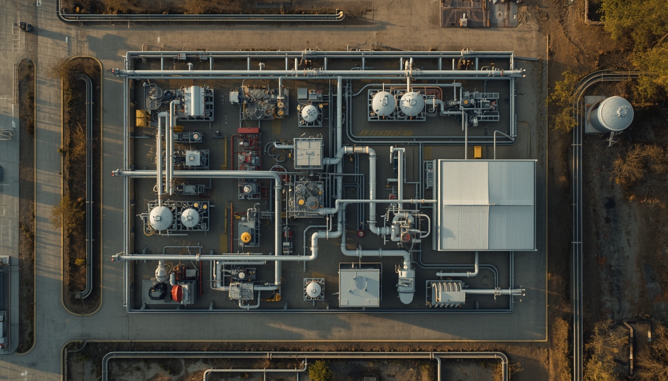
    Plot Plan vs. Equipment Layout

    Two related but distinct documents define a plant’s layout:

    • Plot plan: The site-level arrangement of buildings, roads, major equipment, tanks, utilities, and boundaries.
    • Equipment layout: The detailed arrangement of equipment, piping, and access within a building, structure, or process area.

    For small plants, the plot plan often determines whether the project is feasible at all. Site boundaries, setbacks, access roads, and separation distances are fixed early, and they constrain everything that follows. This article addresses both levels, but the plot plan should be settled before detailed equipment layout begins.

    Why Layout Matters More for Small Plants

    Large plants often have enough space to accommodate imperfect layouts. Small plants do not. Every meter counts. A poorly planned layout in a small plant can lead to:

    • Higher construction cost: Extra piping, longer cable runs, and additional structural steel.
    • Inefficient operations: Longer travel distances for operators and maintenance staff.
    • Safety risks: Inadequate separation between hazardous areas.
    • Limited expansion: No room to add equipment or capacity later.
    • Maintenance difficulties: Equipment that cannot be accessed for service.

    For these reasons, layout should be treated as a strategic decision, not a drafting exercise.

    The Core Objectives of Plant Layout

    Core objectives of industrial plant layout design

    A good layout achieves several objectives simultaneously:

    Objective What It Means
    Minimize capital cost Reduce piping, cabling, and structural requirements
    Optimize operations Place equipment in logical process order
    Ensure safety Separate hazardous areas and provide clear escape routes
    Enable maintenance Provide access for inspection, repair, and replacement
    Allow expansion Reserve space for future equipment or capacity increase
    Facilitate construction Allow efficient sequencing of civil, mechanical, and electrical work

    These objectives sometimes conflict. For example, minimizing cost may push equipment closer together, but safety and maintenance requirements may demand more space. Good layout design balances these trade-offs.

    Key Considerations

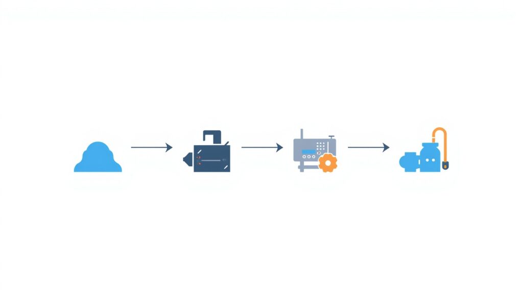
    1. Process Flow

    Process flow diagram for industrial plant layout design

    The layout should follow the process flow as closely as possible. Raw material should enter at one end, and finished product or output should exit at the other. This minimizes piping runs, reduces pressure drops, and simplifies operation.

    For small plants, a linear or L-shaped layout often works best. Linear layouts minimize piping runs and simplify construction, while L-shaped layouts allow the plant to fit into constrained sites while preserving process flow. Both are simple, efficient, and easy to expand.

    2. Equipment Spacing

    Equipment must be spaced to allow:

    • Operation: Space for operators to monitor and adjust equipment.
    • Maintenance: Room to remove and replace components such as heat exchangers, pumps, and motors.
    • Safety: Adequate distance between hot surfaces, electrical equipment, and flammable materials.
    • Ventilation: Airflow to prevent heat buildup and gas accumulation.

    Manufacturers typically provide minimum clearance recommendations. These should be treated as minimums, not targets.

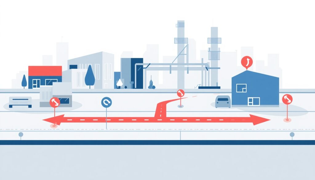
    3. Piping, Pipe Racks, and Cable Routing

    Piping and cabling are significant cost drivers. A layout that minimizes the length and complexity of these runs reduces both capital cost and pressure losses.

    Key principles:

    • Group equipment that shares piping or cabling connections.
    • Use common pipe racks and cable trays where possible.
    • Avoid unnecessary elevation changes in piping.
    • Route cables away from hot or hazardous areas.

    Pipe racks as the backbone of the layout. In many plants, the pipe rack is the organizing element around which everything else is arranged. Its location drives equipment spacing, since equipment is typically placed along both sides of the rack. It also drives construction sequence, because rack foundations and steel are often erected early so that piping and cable trays can be installed as equipment arrives. Deciding rack location and routing early, ideally alongside the plot plan, avoids expensive rework later. Leave spare capacity on the rack for future lines, and keep power and instrument cable trays segregated from process piping according to applicable standards.

    4. Access and Egress

    Safe access is essential. The layout must provide:

    • Primary access routes: For normal operations and maintenance.
    • Emergency egress routes: For evacuation during an incident.
    • Vehicle access: For deliveries, mobile equipment, and emergency response.
    • Pedestrian access: Separate from vehicle routes where possible.

    In small plants, access routes often do double duty. This requires careful planning to avoid conflicts.

    5. Safety, Hazard Separation, and Regulatory Compliance

    Safety should be a primary driver of layout, not an afterthought. Key considerations include:

    • Separation distances: Between hazardous and non-hazardous areas.
    • Fire zones: Segregation of equipment by fire risk.
    • Explosion protection: Location of electrical equipment relative to flammable areas.
    • Toxic gas dispersion: Placement of vents and stacks relative to occupied areas.
    • Emergency shutdown: Access to isolation valves and controls.

    Recognized codes and standards (such as NFPA, IEC, and API) provide guidance on separation distances. These must be respected.

    Regulatory compliance. Local regulations often dictate separation distances, fire zone requirements, and emergency access routes. These must be identified early, as they can constrain the layout significantly. A layout that is efficient on paper but fails a permit review can force a costly redesign.

    6. Maintenance and Replacement

    Equipment must be accessible for maintenance. The layout should allow:

    • Removal of major components: Heat exchanger tubes, turbine rotors, and pump internals.
    • Lifting access: Overhead clearance for cranes or mobile lifting equipment.
    • Workspace: Room for maintenance personnel and tools.
    • Spare parts storage: Nearby but not blocking access.

    For small plants, maintenance access is often compromised by tight layout. This should be addressed early in design, not discovered during operation.

    Operation vs. maintenance. Layout for operation and layout for maintenance sometimes conflict. A compact layout may be efficient for operations but difficult for maintenance. The trade-off should be evaluated explicitly.

    7. Future Expansion

    Even small plants sometimes need to expand. A good layout reserves space for:

    • Additional equipment: Parallel process lines, additional pumps, or extra capacity.
    • Utility upgrades: Larger transformers, additional cooling capacity.
    • Control system expansion: Space for additional panels or instruments.
    • Site infrastructure: Roads, parking, and storage.

    Expansion space should be identified during initial design, even if expansion is not certain.

    8. Construction Sequence

    Layout affects how the plant is built. A layout that allows efficient construction sequencing can reduce schedule and cost. Key considerations include:

    • Access for construction equipment: Cranes, trucks, and heavy lift equipment.
    • Laydown areas: Space for temporary storage of materials and equipment.
    • Sequencing: Ability to install equipment in a logical order without blocking access.
    • Temporary facilities: Site offices, warehouses, and worker facilities.

    For small plants, construction access is often constrained. Early planning helps avoid delays.

    9. 3D Modeling and Clash Detection

    Modern layout design uses 3D modeling to detect clashes between piping, structural, and electrical systems before construction begins. This reduces field changes and rework. In tight small-plant layouts, where piping, steel, cable trays, and maintenance envelopes compete for the same space, clash detection is especially valuable. The 3D model can also be used to check maintenance access and lifting paths, not just physical interferences.

    Common Layout Mistakes

    Even experienced designers make mistakes. Common ones include:

    • Insufficient maintenance access: Equipment installed too close to walls or other equipment.
    • Ignoring expansion: No space reserved for future needs.
    • Poor process flow: Equipment arranged inefficiently, increasing piping and operating cost.
    • Inadequate safety separation: Hazardous areas too close to occupied areas.
    • Overlooking construction access: Equipment that cannot be delivered or installed.
    • Forgetting utilities: Insufficient space for piping, cabling, and instrumentation.

    These mistakes are costly to fix after construction begins. They are much cheaper to avoid during design.

    How Japanese EPC Firms Approach Layout

    Japanese engineering firms often take a disciplined approach to plant layout. Common characteristics include:

    • Thorough front-end planning: Layout is developed early and refined through multiple reviews.
    • Attention to detail: Clearances, access routes, and maintenance space are carefully considered.
    • Safety focus: Hazard separation and emergency access are prioritized.
    • Long-term perspective: Expansion space is reserved even when not immediately needed.
    • Constructability review: Layout is evaluated for ease of construction, not just operation.

    For plant owners, this often means a layout that is efficient, safe, and adaptable to future needs.

    How to Evaluate a Layout

    When reviewing a proposed layout, ask:

    Question Why It Matters
    Does it follow the process flow? Minimizes piping and operating cost
    Is there adequate maintenance access? Reduces downtime and maintenance cost
    Are safety separations respected? Protects people and assets
    Is there space for expansion? Avoids costly future modifications
    Can it be constructed efficiently? Reduces schedule and cost
    Are utilities properly routed? Avoids conflicts and inefficiencies
    Is it compliant with regulations? Ensures legal and safe operation

    A layout that satisfies all these questions is likely to perform well over the plant’s life.

    Conclusion

    Plant layout is not just a drawing exercise. It is a strategic decision that affects cost, safety, operations, and future flexibility. For small-scale industrial plants, where space is limited and margins are tight, layout deserves careful attention from the earliest stages of design.

    By focusing on process flow, equipment spacing, safety, maintenance access, and expansion, owners and designers can create layouts that are efficient, safe, and built to last.

    Key Takeaways

    • Plant layout affects cost, safety, operations, and future flexibility.
    • The plot plan often determines project feasibility, so settle it before detailed equipment layout.
    • Process flow should drive the overall arrangement.
    • Equipment spacing must allow operation, maintenance, and safety.
    • Access and egress must be planned for normal and emergency conditions.
    • Local regulations should be identified early, since they can constrain the layout significantly.
    • 3D modeling and clash detection reduce field changes and rework.
    • Japanese EPC firms emphasize front-end planning and constructability review.