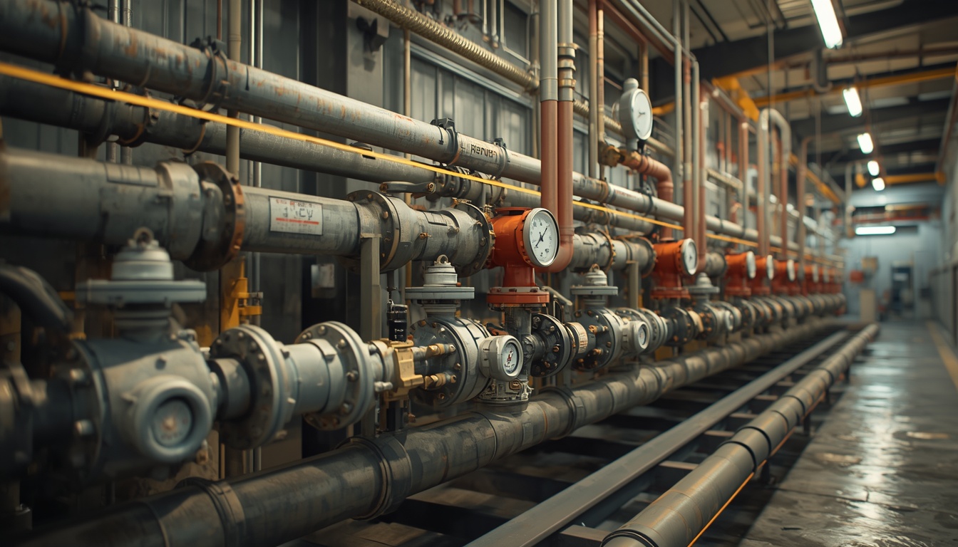
Piping systems are the circulatory system of an industrial plant. They transport fluids—water, steam, fuel, chemicals, and gases—between equipment and processes. A well-designed piping system ensures reliable flow, minimizes pressure loss, and operates safely for decades. A poorly designed system causes pressure drops, vibration, corrosion, and leaks that disrupt operations and create safety hazards.
For small to medium-scale industrial plants, piping design is especially critical because there is less redundancy and fewer resources to manage complexity. Piping often represents a significant portion of total plant cost, and mistakes are expensive to correct after construction.
This article covers the key considerations in piping system design for industrial plants, from material selection to layout, support, and testing.
The Role of Piping Systems
Piping systems perform several essential functions:
- Transport: Moving fluids from one point to another.
- Containment: Keeping fluids safely contained under pressure and temperature.
- Isolation: Allowing sections of the system to be isolated for maintenance or emergencies.
- Control: Working with valves and instruments to regulate flow, pressure, and temperature.
- Protection: Safely relieving excess pressure through relief valves and venting.
Piping is not just a collection of pipes. It is a system that includes pipe, fittings, valves, flanges, gaskets, supports, insulation, and instruments. All components must work together to ensure safe, reliable operation.
Piping Materials
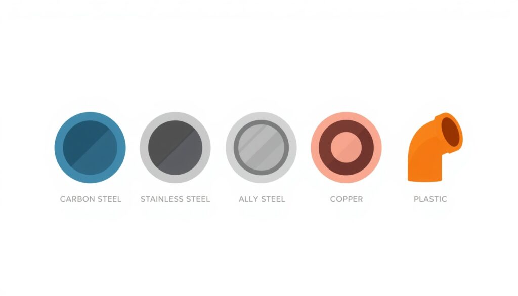
Material selection is one of the most important decisions in piping design. The material must be compatible with the fluid, temperature, pressure, and environment.
Common piping materials include:
| Material | Typical Use | Key Characteristics |
|---|---|---|
| Carbon steel | Steam, water, oil, gas | Strong, economical, but corrodes |
| Stainless steel | Corrosive fluids, high temperature | Corrosion-resistant, expensive |
| Alloy steel | High-temperature, high-pressure service | Retains strength at high temperature |
| Copper | Instrument air, potable water | Corrosion-resistant, but limited temperature range |
| Plastic (PVC, CPVC, HDPE) | Water, chemicals | Corrosion-resistant, limited temperature and pressure |
| Fiberglass reinforced plastic (FRP) | Corrosive chemicals | Corrosion-resistant, lightweight |
Material selection depends on:
- Fluid composition: Corrosive, abrasive, or reactive fluids require special materials.
- Temperature: High temperature reduces material strength and increases corrosion rates.
- Pressure: High pressure requires thicker walls and stronger materials.
- Environment: External corrosion from salt air, chemicals, or soil must be considered.
- Cost: Material cost and life-cycle cost both matter.
Pipe Sizing
Pipe size affects pressure drop, flow velocity, and cost. Pipes that are too small cause excessive pressure drop; pipes that are too large waste material and space.
Key sizing considerations:
- Flow rate: The required flow rate, together with the allowable velocity and pressure drop, determines the pipe size.
- Velocity: Velocity must be high enough to prevent settling but low enough to avoid erosion and noise.
- Pressure drop: Pressure drop must be within acceptable limits for the system.
- Future capacity: Consider whether future flow increases are likely.
Typical velocity guidelines:
| Fluid | Recommended Velocity |
|---|---|
| Water (pump discharge) | 2–4 m/s |
| Water (suction) | 0.5–1.5 m/s |
| Steam (saturated) | 20–40 m/s |
| Compressed air | 10–20 m/s |
| Viscous fluids | 0.5–2 m/s |
These are general guidelines. Specific limits depend on the fluid, material, and application.
Piping Layout
Layout determines how piping is routed through the plant. Good layout minimizes length, avoids conflicts, and allows access for maintenance.
Key layout considerations:
- Route directly: Shorter routes reduce pressure drop and material cost.
- Avoid unnecessary bends: Every bend adds pressure drop and cost.
- Allow for expansion: Piping expands and contracts with temperature changes. Loops, offsets, and expansion joints accommodate this movement.
- Provide access: Valves, instruments, and flanges must be accessible for operation and maintenance.
- Avoid interference: Piping must not interfere with equipment access, walkways, or other systems.
- Slope for drainage: Piping that carries liquids should slope to drain points.
- Consider pipe racks: Grouping pipes in racks saves space and simplifies support.
Expansion joints. Expansion joints (bellows, slip, or articulated) accommodate thermal movement where loops are not practical. However, they require careful design and maintenance because they are a common source of leaks. They must also be properly anchored and guided so that pressure thrust does not overload the joint or the connected equipment.
Pipe Supports
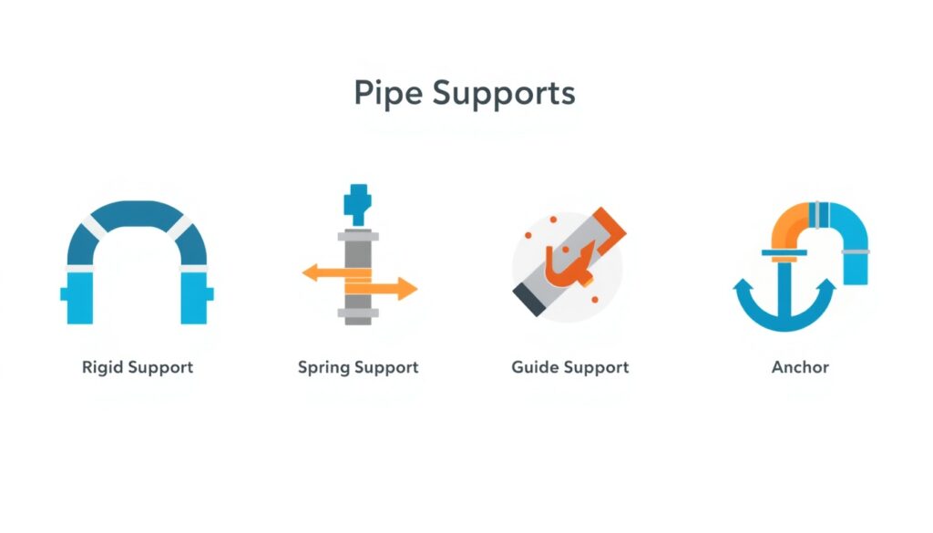
Pipe supports carry the weight of piping and control movement due to thermal expansion, vibration, and other forces.
Types of supports:
- Rigid supports: Carry the weight of the pipe and restrict vertical movement, typically allowing horizontal sliding.
- Spring supports: Allow vertical movement while supporting weight.
- Guide supports: Allow axial movement while preventing lateral movement.
- Anchors: Prevent all movement at a specific point.
- Snubbers: Allow slow movement but resist rapid movement (e.g., during earthquakes).
Support spacing depends on pipe size, material, and contents. Supports must be designed to handle the weight of the pipe, insulation, contents, and any valves or fittings.
Valves and Fittings
Valves control flow and allow isolation. Fittings connect pipes and change direction.
Common valve types:
| Valve Type | Function | Typical Use |
|---|---|---|
| Gate valve | On/off isolation | Fully open or closed service |
| Globe valve | Throttling | Flow regulation |
| Ball valve | On/off isolation | Quick operation |
| Butterfly valve | On/off or throttling | Large diameter, low pressure |
| Check valve | Prevent backflow | Pump discharge, critical lines |
| Control valve | Modulate flow | Process control |
| Relief valve | Protect against overpressure | Pressure vessels, piping systems |
Common fitting types:
- Elbows: Change direction.
- Tees: Branch flow.
- Reducers: Change pipe size.
- Flanges: Connect pipes and equipment for disassembly.
Insulation and Heat Tracing
Insulation reduces heat loss or gain and protects personnel from hot or cold surfaces.
Insulation considerations:
- Thermal performance: Insulation thickness depends on temperature and desired performance.
- Personnel protection: Surfaces above 60°C or below 0°C typically require insulation or guarding.
- Corrosion under insulation (CUI): Insulation can trap moisture and cause corrosion. Proper design and maintenance are essential.
- Heat tracing: Electric or steam tracing maintains temperature in pipes that would otherwise cool below required levels.
Pipe Identification and Labeling
In complex plants, pipes must be identifiable for operation and maintenance. Pipes should be labeled with their contents and flow direction. Color coding and labeling systems help operators and maintenance staff identify lines quickly.
Pressure Relief and Safety
Piping systems must be protected against overpressure. Relief valves, rupture discs, and venting systems prevent catastrophic failure.
Key considerations:
- Relief valve sizing: Must be sized to handle the maximum relief case.
- Discharge location: Relief discharge must be routed to a safe location.
- Testing: Relief valves must be tested periodically.
- Documentation: Relief valve sizing, testing, and maintenance must be documented.
Water Hammer
Water hammer occurs when fluid flow is suddenly stopped or changed, causing pressure surges that can damage piping and supports. Common causes include fast-closing valves and pump trips. Proper design includes slow-closing valves, air chambers, and surge suppressors.
Testing and Commissioning
Piping systems must be tested before operation to verify integrity and safety.
Common tests:
- Hydrostatic test: Fills the system with water and pressurizes to test strength and leak tightness.
- Pneumatic test: Uses air or inert gas instead of water (used when water is not suitable). Because compressed gas stores much more energy than water, pneumatic tests require additional safety precautions.
- Flushing: Removes debris and contaminants from the system.
- Cleaning: Removes scale, rust, and other deposits.
- Leak test: Verifies that joints and connections do not leak.
Testing must be documented and witnessed where required.
Key Design Considerations
1. Codes and Standards
Piping systems must comply with applicable codes and standards, such as ASME B31.1 (power piping), ASME B31.3 (process piping), or local equivalents.
2. Material Compatibility
Materials must be compatible with the fluid, temperature, and environment. Incompatible materials cause corrosion, contamination, or failure.
3. Flexibility and Stress Analysis
Piping must accommodate thermal expansion and other movements without excessive stress. Stress analysis may be required for critical lines. It is typically performed using specialized software such as CAESAR II or AutoPIPE. These tools model the piping system, apply thermal and mechanical loads, and calculate stresses at critical points.
4. Support and Restraint
Supports must carry weight and control movement. Restraints must prevent excessive movement without over-stressing the pipe.
5. Accessibility
Valves, instruments, and flanges must be accessible for operation and maintenance. Piping should not block access to equipment.
6. Future Expansion
Piping systems should be designed with spare capacity for future additions. This includes spare nozzles, spare pipe racks, and spare valves.
Common Mistakes in Piping Design
Even experienced designers make mistakes. Common ones include:
- Undersizing pipes: Causing excessive pressure drop and poor performance.
- Ignoring thermal expansion: Leading to stress, deformation, or failure.
- Inadequate support spacing: Causing sagging, vibration, or failure.
- Poor access to valves and instruments: Making maintenance difficult.
- Incompatible materials: Causing corrosion or contamination.
- Missing relief protection: Creating a safety hazard.
- Ignoring water hammer: Allowing pressure surges to damage piping and supports.
- Insufficient documentation: Making maintenance and troubleshooting difficult.
These mistakes are costly to fix after construction. They are much cheaper to avoid during design.
How Japanese EPC Firms Approach Piping Design
Japanese engineering firms are known for their disciplined approach to piping design. Common characteristics include:
- Thorough stress analysis: Critical lines are analyzed carefully for thermal and mechanical stress.
- Conservative material selection: Materials are selected with adequate margin for corrosion and temperature.
- Detailed support design: Supports are designed for all expected loads and movements.
- Comprehensive documentation: Piping drawings, isometrics, and test records are carefully maintained.
- Long-term reliability focus: Designs prioritize reliability and maintainability over lowest initial cost.
For plant owners, this often means a piping system that performs reliably for decades, with fewer leaks and less maintenance.
How to Evaluate Piping Design
When reviewing piping design, ask:
| Question | Why It Matters |
|---|---|
| Are pipes sized for actual flow and pressure drop? | Ensures proper performance |
| Are materials compatible with the fluid and environment? | Prevents corrosion and failure |
| Is thermal expansion accommodated? | Prevents stress and deformation |
| Are supports designed for all loads? | Prevents sagging and vibration |
| Are valves and instruments accessible? | Enables operation and maintenance |
| Has water hammer been assessed and controlled? | Prevents pressure-surge damage |
| Is relief protection provided? | Prevents overpressure failure |
| Does the design comply with applicable codes? | Ensures safety and legal operation |
A design that addresses these questions is likely to perform well over the plant’s life.
Conclusion
Piping systems are essential to plant reliability, safety, and efficiency. For small to medium-scale industrial plants, piping design deserves careful attention from the earliest stages of design. By focusing on material selection, sizing, layout, support, stress analysis, surge protection, and testing, owners and designers can ensure reliable flow and safe operation for decades.
Key Takeaways
- Piping systems transport, contain, isolate, control, and protect
- Material selection depends on fluid, temperature, pressure, and environment
- Pipe sizing balances pressure drop, velocity, and cost
- Layout should minimize length, avoid bends, and allow for expansion
- Supports carry weight and control movement
- Testing verifies integrity before operation
- Japanese EPC firms emphasize thorough stress analysis and detailed support design