
Electrical systems are the nervous system of an industrial plant. They power motors, control instruments, provide lighting, and ensure safety systems function when needed. Unlike mechanical systems, which can sometimes be bypassed or operated manually, electrical systems must operate correctly every time. A failure can shut down the entire plant—or worse, create a safety hazard.
For small to medium-scale industrial plants, electrical system design is especially critical because there is less redundancy and fewer resources to manage complexity. The right design ensures reliable power, safe operation, and room for future expansion.
This article covers the key considerations in electrical system design for industrial plants, from power supply to distribution, protection, and control.
The Main Electrical Systems in an Industrial Plant
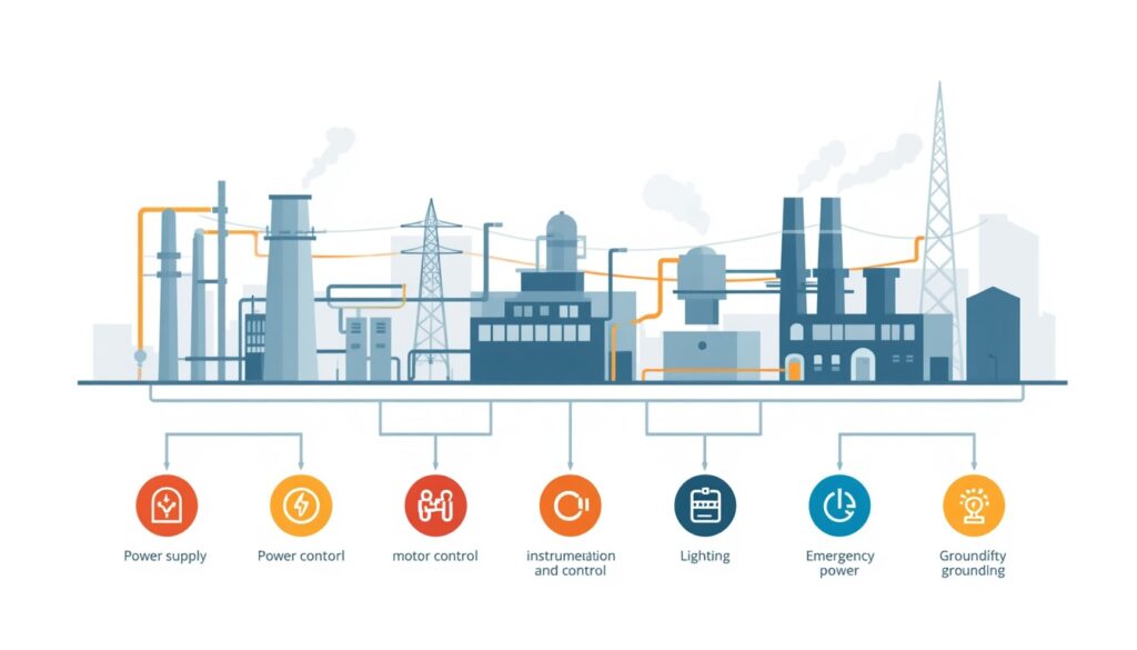
An industrial plant’s electrical system can be divided into several subsystems, each with its own function.
| System | Purpose |
|---|---|
| Power supply | Receives power from the grid or on-site generation |
| Power distribution | Delivers power to equipment throughout the plant |
| Motor control | Starts, stops, and protects motors |
| Instrumentation and control | Monitors and controls process variables |
| Lighting | Provides illumination for operation, maintenance, and safety |
| Emergency power | Provides backup power for critical systems |
| Grounding and lightning protection | Protects people and equipment from electrical hazards |
Each subsystem must be designed to work with the others. A weakness in any one can compromise the entire plant.
Power Supply
The first decision in electrical system design is how the plant will receive power.
Grid supply: Most industrial plants receive power from the local utility grid. The supply voltage depends on the utility and the plant’s size. Small plants may receive power at low voltage (e.g., 400 V or 480 V), while larger plants receive power at medium voltage (e.g., 6.6 kV, 11 kV, or 33 kV) and step it down on site.
On-site generation: Some plants generate their own power using gas turbines, diesel generators, or renewable sources. This provides independence from the grid but adds complexity and cost.
Combined supply: Many plants use both grid supply and on-site generation. This provides redundancy and allows the plant to operate during grid outages.
Key considerations for power supply:
- Reliability: How often does the grid fail, and how long do outages last?
- Power quality: Voltage sags, harmonics, and frequency variations can affect equipment.
- Cost: Tariff structures, demand charges, and time-of-use rates affect operating cost.
- Future expansion: Will the plant need more power later?
Power Distribution
Once power enters the plant, it must be distributed to equipment throughout the site.
Distribution voltages: Plants typically use multiple voltage levels:
- Medium voltage (e.g., 6.6 kV, 11 kV, 33 kV): For distribution across the site and to large motors.
- Low voltage (e.g., 400 V, 480 V): For small motors, lighting, and control systems.
- Extra-low voltage (e.g., 24 V DC): For instrumentation and control.
Transformers step voltage down between levels.
Distribution configurations:
| Configuration | Characteristics | Typical Use |
|---|---|---|
| Radial | Simple, single path from source to load | Small plants, non-critical loads |
| Ring | Power feeds from two directions | Medium plants, improved reliability |
| Network | Multiple sources and paths | Large plants, high reliability |
For small to medium-scale plants, radial distribution is often sufficient. Ring distribution may be justified for critical loads.
Key considerations for power distribution:
- Voltage drop: Long cable runs cause voltage drop, which affects motor performance.
- Cable sizing: Cables must be sized for current, voltage drop, and short-circuit withstand.
- Routing: Cables should be routed away from hot surfaces, moisture, and mechanical damage.
- Segregation: Power and instrument cables should be segregated to avoid interference.
Power factor correction: Many utilities charge penalties for low power factor. Power factor correction capacitors or synchronous condensers may be required to maintain power factor above a specified threshold.
Harmonics and filtering: Non-linear loads such as VFDs and rectifiers generate harmonics that can distort voltage and affect sensitive equipment. Harmonic filters or active compensators may be required.
Motor Control
Motors are the largest electrical loads in most industrial plants. They drive pumps, fans, compressors, and conveyors.
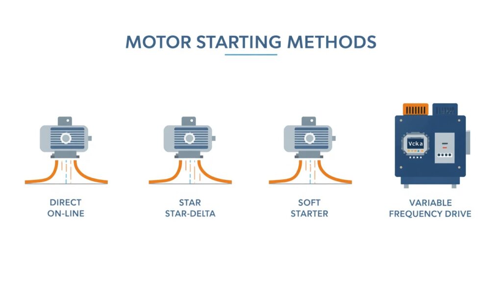
Motor starting: Large motors draw high starting current, which can cause voltage dips. Starting methods include:
- Direct-on-line (DOL): Simple but high starting current.
- Star-delta: Reduces starting current but adds complexity.
- Soft starter: Gradually increases voltage to reduce starting current.
- Variable frequency drive (VFD): Controls motor speed and torque, with low starting current.
Motor protection: Motors must be protected against:
- Overload: Excessive current due to mechanical or electrical faults.
- Short circuit: Faults that cause very high current.
- Phase loss: Loss of one phase in a three-phase supply.
- Earth fault: Current leaking to ground.
Protection devices include overload relays, circuit breakers, and earth fault relays.
Key considerations for motor control:
- Starting method: Depends on motor size, load characteristics, and grid strength.
- Protection coordination: Protection devices must coordinate to isolate faults without unnecessary trips.
- Control philosophy: Local vs. remote control, manual vs. automatic operation.
Instrumentation and Control
Instrumentation and control systems monitor process variables and adjust equipment to maintain desired conditions.
Control system types:
| Type | Characteristics | Typical Use |
|---|---|---|
| Relay logic | Simple, hardwired | Small plants, simple processes |
| PLC | Programmable, flexible | Most industrial plants |
| DCS | Distributed, integrated | Large, complex plants |
| SCADA | Supervisory control and data acquisition | Plants requiring remote monitoring |
For small to medium-scale plants, PLC-based control is common. It offers flexibility and is well-supported by vendors.
Key considerations for instrumentation and control:
- Signal types: Analog (4–20 mA), digital, and fieldbus communications.
- Redundancy: Critical control loops may require redundant sensors or controllers.
- Cybersecurity: Control systems are increasingly connected to networks, creating security risks.
- Human-machine interface (HMI): Operators need clear, intuitive displays.
Lighting
Lighting is often overlooked but essential for safe operation and maintenance.
Lighting types:
- General lighting: Illuminates work areas.
- Task lighting: Provides focused light for specific tasks.
- Emergency lighting: Provides illumination during power failures.
- Outdoor lighting: Illuminates access roads, storage areas, and perimeters.
Key considerations for lighting:
- Illumination levels: Depends on the task and area.
- Energy efficiency: LED lighting reduces power consumption.
- Emergency lighting: Must be powered by backup supply.
- Maintenance access: Light fixtures must be accessible for replacement.
Emergency Power
Emergency power systems provide backup power for critical loads during grid outages.
Emergency power sources:
- Diesel generators: Common, reliable, but require fuel storage and maintenance.
- Battery systems: Provide instant power for short outages.
- Uninterruptible power supplies (UPS): Provide clean, continuous power for sensitive equipment.
Critical loads requiring emergency power:
- Safety systems (fire detection, emergency shutdown)
- Control systems
- Emergency lighting
- Critical instrumentation
- Communication systems
Key considerations for emergency power:
- Load list: Which loads require backup power?
- Duration: How long must backup power last?
- Startup time: How quickly must backup power come online?
- Testing: Emergency systems must be tested regularly.
Grounding and Lightning Protection
Grounding and lightning protection protect people and equipment from electrical hazards.
Grounding: Grounding provides a low-resistance path for fault current, allowing protection devices to operate quickly. It also stabilizes voltage and reduces electrical noise.
Lightning protection: Lightning protection systems intercept lightning strikes and conduct them safely to ground. They include air terminals, down conductors, and grounding electrodes.
Key considerations:
- Grounding system design: Must be designed for the site’s soil conditions.
- Bonding: All metallic structures and equipment must be bonded to the grounding system.
- Testing: Grounding systems must be tested periodically.
Arc flash safety: Arc flash studies identify areas where high-energy electrical faults could occur. Appropriate labeling, PPE requirements, and work procedures must be in place.
Key Design Considerations
1. Load Analysis
The first step in electrical design is a load analysis. This determines the total connected load, demand load, and future load.
2. Redundancy
Critical systems may require redundant power supplies, transformers, or feeders. The level of redundancy depends on the consequences of failure.
3. Protection Coordination
Protection devices must coordinate so that the device closest to a fault operates first, minimizing disruption.
4. Cable Routing and Segregation
Power and instrument cables should be routed separately to avoid interference. Cables should be protected from heat, moisture, and mechanical damage.
5. Safety
Electrical systems must comply with applicable codes and standards (e.g., IEC, NEC, local regulations). Safety features include grounding, isolation, and lockout/tagout provisions.
6. Future Expansion
Electrical systems should be designed with spare capacity for future loads. This includes spare breakers, spare cable trays, and spare transformer capacity.
7. Electrical System Studies
Electrical system studies include load flow analysis, short circuit analysis, protection coordination, and arc flash analysis. These studies should be completed during design and updated as the system changes.
Common Mistakes in Electrical System Design
Even experienced designers make mistakes. Common ones include:
- Undersizing equipment: Leading to overloads and failures.
- Ignoring voltage drop: Causing poor motor performance.
- Poor protection coordination: Leading to unnecessary trips or failure to isolate faults.
- Inadequate grounding: Creating safety hazards and equipment damage.
- No spare capacity: Requiring costly upgrades for future expansion.
- Insufficient segregation: Causing electrical noise and interference.
These mistakes are costly to fix after construction. They are much cheaper to avoid during design.
How Japanese EPC Firms Approach Electrical System Design
Japanese engineering firms are known for their disciplined approach to electrical system design. Common characteristics include:
- Thorough load analysis: Loads are analyzed carefully, with margin for future growth.
- Conservative design margins: Equipment is sized with adequate margin for worst-case conditions.
- Detailed protection coordination: Protection settings are carefully studied and coordinated.
- Comprehensive documentation: Drawings, schedules, and test records are carefully maintained.
- Long-term reliability focus: Designs prioritize reliability and maintainability over lowest initial cost.
For plant owners, this often means an electrical system that performs reliably for decades, with fewer unplanned outages.
How to Evaluate Electrical System Design
When reviewing electrical system design, ask:
| Question | Why It Matters |
|---|---|
| What is the total connected load and demand load? | Determines equipment sizing |
| What is the power supply configuration? | Affects reliability and cost |
| Is redundancy provided for critical loads? | Ensures continued operation during faults |
| How is protection coordinated? | Minimizes disruption from faults |
| How are cables routed and segregated? | Avoids interference and damage |
| Is there spare capacity for future expansion? | Avoids costly upgrades later |
| Does the design comply with applicable codes? | Ensures safety and legal operation |
A design that addresses these questions is likely to perform well over the plant’s life.
Key Takeaways
- Electrical systems are critical to plant reliability, safety, and efficiency
- Power supply can be from the grid, on-site generation, or both
- Distribution configurations include radial, ring, and network
- Motor starting methods include DOL, star-delta, soft starter, and VFD
- Emergency power is required for safety, control, and critical instrumentation
- Japanese EPC firms emphasize thorough load analysis and protection coordination
Conclusion
Electrical systems are critical to plant reliability, safety, and efficiency. For small to medium-scale industrial plants, electrical design deserves careful attention from the earliest stages of design. By focusing on load analysis, redundancy, protection, safety, and future expansion, owners and designers can ensure reliable power and safe operation for decades.